

Content last revised on September 19, 2026
Transient Dynamics & Electrical Design: Dynamic Gate Impedance Control for Robust Operation
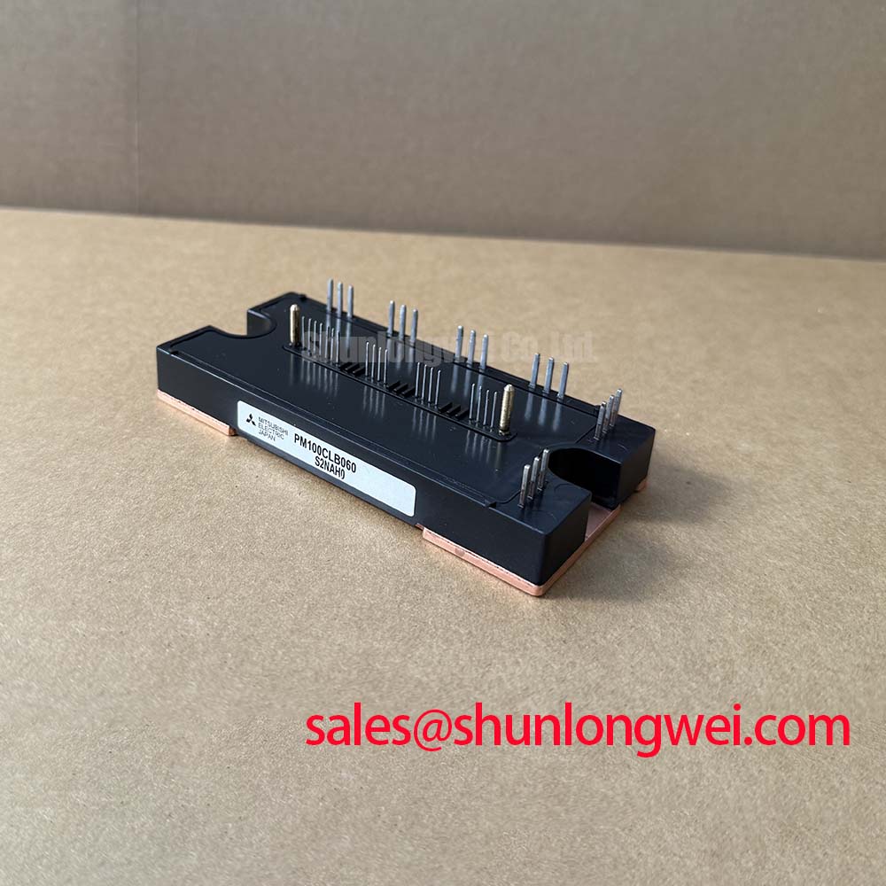
Begin a service evaluation by confirming the nameplate boundary, inspecting the insulated power package for visible damage, and checking the disconnected power terminals for unintended low impedance before reconnecting the drive. The PM100CLB060 is a Mitsubishi Electric IPM module with an official rated voltage of 600 V and an official rated current of 100 A. These are the primary product identity parameters supplied for this listing; the complete inverter operating envelope remains dependent on switching frequency, cooling, duty cycle, protection settings, and the original equipment design.
In a heavy-duty variable frequency AC motor drive, the module’s integrated gate-drive and protection circuitry must be evaluated as part of the complete commutation loop. A high common-mode transition can couple into the opposite control path through parasitic capacitance. The resulting gate disturbance may reduce switching margin or contribute to cross-conduction, but the symptom should not be assigned to the IPM alone without checking the driver supply, control return, control wiring, isolation interface, and oscilloscope probe arrangement.
Design Consideration: use the shortest practical control and return paths, maintain a controlled relationship between power-current paths and control wiring, and keep high-current switching nodes away from sensitive logic traces. If the design provides access to relevant internal gate nodes, designers evaluating active Miller-clamp behavior or negative turn-off bias should verify the required gate-voltage limits from the original Mitsubishi Electric documentation and the drive schematic. The values suggested in a general application discussion must not be treated as confirmed PM100CLB060 ratings.
For commissioning, observe the available control-input and fault-feedback waveforms at the module terminals with suitable differential measurement equipment. Compare the high-side and low-side behavior during turn-on, turn-off, fault shutdown, and restart. Internal gate waveforms should only be measured where the module or test design provides appropriate access. A waveform that differs substantially between a known-good assembly and the service unit may indicate layout parasitics, an unsuitable probe connection, driver saturation, isolation timing error, or damage elsewhere in the power stage. Verify the complete signal path before changing gate resistance or bias conditions.
The power interface also deserves a measured review. The positive and negative DC-link conductors should follow a compact, symmetrical route where practical, while motor-phase conductors should be separated from low-level feedback wiring. Clearance around the switching terminals must be determined from the working voltage, pollution environment, insulation system, and applicable equipment standard. The IPM rating does not independently certify the finished drive for EMC, electrical safety, or insulation coordination.
When the module is being considered for repair rather than a new design, record the original gate resistor arrangement, driver supply behavior, fault timing, and current-sensor response before modifying the circuit. The Mitsubishi Electric power semiconductor reference resources provide manufacturer-level context for evaluating power modules, while the exact replacement decision should remain tied to the original equipment documentation.
Benchtop Waveform Tuning: DC-Link Layout, MOV Coordination, and Switching Stress
Waveform testing should start with the DC-link at a controlled condition and with the protection network documented. A metal-oxide varistor can support surge absorption at the equipment level, but its voltage rating, energy capability, leakage behavior, and coordination with the DC-link capacitor bank must be selected for the actual bus voltage and transient profile. The MOV is not a substitute for a properly positioned local capacitor, an appropriate semiconductor fuse, or validated overvoltage protection.
During turn-off, stray inductance in the commutation path can convert rapid current change into voltage overshoot. In engineering terms, the observed peak is influenced by the DC-link voltage, loop inductance, current slew rate, damping, measurement bandwidth, and the location of the probe reference. The correct acceptance limit must be established by the system designer against the 600 V official rating, operating temperature, repetitive switching duty, and the applicable Mitsubishi Electric data. Do not use a calculated transient value as a guaranteed safe operating limit without a controlled switching test.
A practical benchtop sequence is to verify the DC-link voltage at the module terminals, inspect capacitor polarity and busbar joints, then capture collector-emitter voltage and phase current at the same time. Repeat the measurement with the intended motor cable, filter, and braking arrangement in place. A clean waveform at the laboratory busbar may change after the cabinet, cable harness, and motor are connected. Use the same probe locations when comparing a service unit with a known-good drive.
Symmetrical planar busbar geometry can reduce the area of the high-current commutation loop. The design target should be established from the equipment switching speed and measured overshoot rather than copied from a generic layout rule. Local DC-link capacitance should be positioned to serve the switching loop, with the capacitor technology, ripple-current capability, ESR, ESL, and thermal environment checked as a complete network.
The fast semiconductor fuse must also be coordinated with the module and the DC-link source. Its available I²t, clearing behavior, prospective fault current, and interrupting capability should be compared with the protection requirements of the finished drive. Fuse coordination cannot be inferred from the 100 A module current rating alone. A dead-short event may involve wiring inductance, capacitor discharge, driver shutdown delay, and mechanical fault-clearing time, so the protection study should use measured or documented system data.
Thermal interface preparation affects the electrical test result indirectly because case temperature changes switching behavior and protection margin. Apply the interface material uniformly according to the selected heatsink and material supplier instructions, remove contamination from both mating surfaces, and tighten fasteners in a controlled cross-pattern sequence. The correct torque is an assembly specification determined by the module hardware, heatsink, washer arrangement, and manufacturer documentation rather than a universal PM100CLB060 rating.
⚠️ Field Alert: isolate the DC link and verify residual voltage before disconnecting the module, control harness, or current-sensing wiring.
Field Diagnostics & Commissioning: Protection Boundaries in Variable Frequency Drives
At the service bench, separate a control fault from a power-stage fault by testing the driver supply, enable logic, fault feedback, and phase output response in a controlled sequence. Do not apply full bus voltage to a repaired assembly until the gate timing, interlock behavior, precharge circuit, braking path, and current feedback have been checked. A failed start command, repeated protection trip, or unbalanced phase waveform can have several possible sources, including the upstream rectifier, DC-link capacitors, gate driver, motor cable, load, or the IPM itself.
For equipment operated at elevated locations, atmospheric radiation and reduced cooling conditions may be considered as part of a system reliability review, but no specific FIT rate, single-event burnout probability, altitude derating curve, or operating lifetime should be assigned to the PM100CLB060 without an authoritative source. The safe approach is to verify the applicable manufacturer qualification data and then assess the actual DC-bus voltage, junction temperature, switching stress, and enclosure cooling against that information.
Voltage headroom should be treated as a measured design variable. Engineers can record the highest repetitive collector-emitter transient during acceleration, deceleration, regeneration, and fault interruption, then compare it with the documented rating under the relevant temperature and duty conditions. If the measurement approaches the equipment limit, review bus regulation, braking energy, cable inductance, MOV coordination, snubber placement, gate timing, and load conditions before selecting a different protection setting.
The module’s official identity for this page is concise: Mitsubishi Electric PM100CLB060, 600 V rated voltage, 100 A rated current, and Mitsubishi IPM Module package. Other characteristics such as isolation performance, built-in protection functions, terminal assignments, switching limits, and thermal impedance should be confirmed from the applicable original technical documentation rather than inferred from the product name.
For a replacement assessment, compare the original equipment’s mounting pattern, electrical terminals, control interface, protection sequence, and thermal path. The CM100DY-12E may be reviewed as a separate Mitsubishi Electric power-module option, but its suitability must be established from its own ratings and mechanical configuration. It should not be treated as an automatic substitute for the PM100CLB060.
In a front-end power architecture, the associated rectifier and DC-link arrangement can strongly affect the stress seen by the inverter IPM. Engineers may examine the CM300DXDX1-24A as a separate related component for topology analysis, while confirming voltage, current, protection, and mounting compatibility independently. This neutral comparison helps identify the actual system boundary instead of assuming that a similar product label provides functional equivalence.
Assembly Integrity & Layout Architecture: Thermal Network Verification
Thermal commissioning should begin with the complete heat path: semiconductor case interface, thermal compound or pad, heatsink flatness, fastener loading, airflow, cabinet temperature, and switching duty. The official 100 A current rating is not a universal continuous-current guarantee for every installation. Allowable current depends on the specified conditions and the thermal network established by the equipment designer.
A junction-to-case thermal model can be used as an engineering calculation when its resistance and transient constants come from the applicable manufacturer documentation. The model should be driven with the actual loss waveform, including conduction loss, switching loss, regeneration, overload duration, and control-cycle repetition. A single average current value may conceal short overload pulses that raise junction temperature before the heatsink responds.
When validating a repaired heavy-duty drive, measure heatsink temperature at several operating points and correlate it with phase current, carrier frequency, acceleration profile, and ambient conditions. Infrared readings require attention to emissivity and surface condition; a thermocouple or embedded sensor may provide a more useful comparative trend when installed consistently. These measurements support a thermal assessment but do not replace the manufacturer’s transient thermal data.
The mechanical interface should be inspected after thermal cycling. Look for uneven compound spread, displaced insulation, loose fasteners, distorted washers, contamination, or stress around the module base. The mounting surface should remain clean and stable, and the clamping process should follow the hardware supplier’s sequence. Designers should also confirm that the heatsink does not impose mechanical force on power terminals or control connectors.
For battery-connected bidirectional DC-to-DC equipment, repeated charge and discharge cycles can alter the thermal profile, capacitor ripple, and bus transient pattern. This product page does not establish a battery-cycle lifetime for the PM100CLB060. The system engineer should evaluate the thermal cycle, dwell time, regeneration energy, cooling recovery, and protection response using the actual converter control strategy and documented device limits.
When the test involves a new layout, repair engineers can use the practical guidance in IGBT Design & Integration to organize gate-drive, thermal-management, and circuit-topology checks. The final acceptance decision should come from measured switching waveforms, verified insulation distances, protection coordination, and thermal results for the finished equipment.
Before release, document the module identity, measured bus voltage, phase-current conditions, control waveform observations, fault response, heatsink temperature, and any changes made to the original assembly. This record gives the maintenance team a repeatable basis for future PM100CLB060 service evaluation without converting general design guidance into an unverified product guarantee.