Content last revised on October 15, 2026
Preventing Spurious Faults: Oscilloscope Waveform Verification for PM50B4L1C060
When a heavy duty variable frequency AC motor drive reports an intermittent overcurrent or gate fault, disconnect and discharge the DC link before inspecting the control and drive-supply paths or installing a replacement module. During powered testing, check the control input, control return reference, and switching waveform with a properly rated differential probe so that ringing is not confused with a genuine protection event.
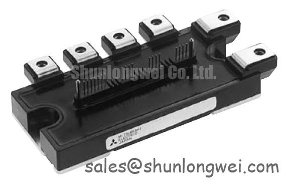
The PM50B4L1C060 is a Mitsubishi Electric IPM module in the 600 V, 50 A class, with integrated gate-drive circuitry. These device ratings are not recommended DC-link voltage or continuous operating current values. The actual DC link, switching frequency, protection requirements, and thermal conditions must be determined from the applicable device documentation and complete drive design.
| Manufacturer | Mitsubishi Electric |
| Part number | PM50B4L1C060 |
| Product category | IPM intelligent power module |
| Collector-emitter voltage rating | 600 V |
| Collector current rating | 50 A under the manufacturer's specified conditions |
| Package | Mitsubishi IPM module |
During retrofit work, the integrated gate-drive circuitry should be treated as part of the module. External control-input resistors are not equivalent to discrete IGBT turn-on and turn-off gate resistors. A Design Consideration is to inspect the control interface and supply decoupling while observing collector-emitter voltage, phase current, control-input signals, and fault timing together.
Probe placement matters. Keep the measurement loop short, use the reference point specified for the measured signal, and compare the suspect phase with a known-good phase under the same operating condition. Excessive ringing at a control input may point to common-mode reference movement, control-loop inductance, or an unsuitable interface circuit. A fault that appears only during motor acceleration should also be compared with the DC-link waveform and current feedback signal before changing the module.
For field replacement planning, the PM30CNA060 is a separate product, and no replacement compatibility is established here. Any proposed substitute requires electrical, mechanical, control-interface, and protection compatibility checks before testing the complete inverter assembly.
Preventing Spurious Faults: Isolated DC-DC Power Supply Sizing for High dv/dt Gate Drive Conditions
Gate-drive power supplies should be checked for isolation integrity, transient immunity, and load behavior before the PM50B4L1C060 is energized in a repaired inverter. The isolated supply must maintain the module's required control-supply voltage during switching transients, while the control interface must prevent common-mode disturbances from causing unintended switching commands.
For a Design Consideration, review the isolation barrier rating and common-mode transient performance of the isolated DC-DC converter together with the optocoupler or digital isolator used in the control interface. Any isolation withstand or CMTI values must come from the selected components' datasheets; they are not presented here as official specifications of the PM50B4L1C060 itself. The system engineer should verify the required withstand level against the drive’s switching environment and safety architecture.
Inspect the isolated secondary return path carefully. A long return trace between the isolated supply and the module can convert common-mode current into a local reference disturbance. Keep supply decoupling and the associated return paths compact, while keeping high-current commutation paths physically separated from sensitive control traces. Use the supply polarity and voltage range specified for the module; external negative gate-bias arrangements used with discrete IGBTs should not be applied to its control terminals.
Power-up testing should be performed with the DC link disabled and discharged. Confirm that the isolated supply reaches its intended operating state without repeated start-up cycling, excessive ripple, or cross-channel imbalance. Then observe the control inputs and power-stage switching waveforms during low-energy switching before applying the normal motor-drive bus voltage. This sequence helps distinguish a defective power supply from an internal module fault or a layout-related common-mode disturbance.
The thermal interface between the module base and heatsink also influences the power-stage test result. Use a uniform, controlled interface layer and ensure that the mounting surface is clean, flat, and free of particles. A cross-pattern tightening sequence is a Design Consideration for distributing mounting pressure, but the final torque must follow the applicable mechanical documentation for the module, fastener, and heatsink assembly.
Engineers reviewing other power-stage options may also encounter the PM300CLA060. Its electrical role, topology, and ratings must be assessed independently; its inclusion here does not establish suitability as a rectifier or as a replacement for the PM50B4L1C060.
PM50B4L1C060 Operational Boundaries: Thermal Paste Control and Mounting Limits
Thermal performance begins at the mechanical interface, so examine the heatsink contact surface before applying compound to the PM50B4L1C060. A thin and continuous thermal interface layer is generally preferred because excessive compound can increase thermal resistance, while insufficient coverage can leave air pockets beneath the module base.
For general installation practice, a controlled TIM thickness in the approximate range of 50 to 100 µm may be used as a starting reference only, not as an official Mitsubishi Electric specification. The correct amount depends on the compound, surface flatness, baseplate condition, and clamping method. Spread the material evenly enough to cover the contact area without creating thick ridges or isolated voids.
Baseplate curvature should be considered before final tightening. If the module or heatsink does not sit evenly, tightening one corner first can create localized pressure and reduce contact elsewhere. Use the fastener arrangement specified for the assembly, bring the screws down progressively in the specified sequence, and confirm that the heatsink remains aligned as pressure increases.
After mounting, inspect the interface condition if the module has experienced abnormal thermal behavior. Uneven compound transfer, dry regions, displaced material, or visible contamination can indicate poor contact, but these observations should be correlated with measured temperature, current, switching duty, and airflow. Thermal paste aging is influenced by temperature cycling, mechanical movement, compound chemistry, and enclosure conditions rather than by elapsed time alone.
Field Alert: Disconnect the DC link and gate-drive supplies before removing connectors or touching the IPM terminals, allow the specified discharge period for the complete drive assembly, and verify that hazardous voltage is absent.
If parallel operation is supported by the applicable device documentation, positive temperature coefficient behavior at the relevant operating point can assist static current sharing. Dynamic sharing still depends on matched switching timing, symmetrical busbar geometry, common impedance, and switching behavior. Parallel operation should therefore be validated through current-probe measurements during turn-on, turn-off, overload response, and regenerative conditions rather than inferred from rated current alone.
Field Diagnostics and Commissioning: Pre-Installation Junction Health Check
Cold bench screening should be completed before the PM50B4L1C060 is connected to an energized DC link. With all external supplies removed and the DC link discharged, use a digital multimeter in diode-check mode to compare the main semiconductor paths and antiparallel diode paths identified by the module’s terminal configuration. The readings should be assessed for consistent directional behavior between comparable phases rather than judged by an unsupported universal threshold.
Because the gate-drive circuitry is integrated, a meter check at a control input does not directly measure IGBT gate-emitter resistance or gate leakage. Use the manufacturer's recommended terminal checks to screen for shorts or abnormal readings. A significant asymmetry may justify further testing, but a meter result alone cannot identify every failure mode. Internal driver circuitry, contamination, parallel circuit paths, and measurement lead configuration can all affect the result.
Inspect the power terminals, control connector, mounting base, and insulation barriers for mechanical damage or signs of overheating. Verify that the module is seated correctly and that no busbar, screw, washer, or cable shield can contact an unintended terminal. The package is identified as a Mitsubishi IPM module, so the correct terminal assignment and control sequence must be taken from the applicable device documentation and the original drive schematic.
Commissioning should proceed with the lowest practical stored energy and current limit available in the test setup. Monitor phase current, control inputs, control-supply voltage, collector-emitter voltage, fault output behavior, and heatsink temperature as a coordinated set. Verify the documented protection and fault-response behavior using the manufacturer's recommended test procedures. Short-circuit withstand capability and required fault-clearing timing must be taken from the device documentation and should not be inferred from the 50 A current rating.
When several modules or phases operate together, inspect the control return routing for common-mode ground bounce. Shield sensitive control references from high di/dt commutation paths, minimize unnecessary loop area, and verify the result with differential probing at the accessible module terminals. The practical principles discussed in Precision Gate Drive Design can support the review of transient measurement methods and switching-related interference, while the PM50B4L1C060 control interface must follow its own documentation.
For broader semiconductor technology context, engineers can consult Mitsubishi Electric’s SiC Power Modules and SBDs resource. That material concerns a different device technology and should be used for general power-semiconductor reference, not as a substitute for the PM50B4L1C060 documentation.