Content last revised on September 17, 2026
Transient Dynamics & Electrical Design: Active Miller Clamp Implementation on PM50CSD060
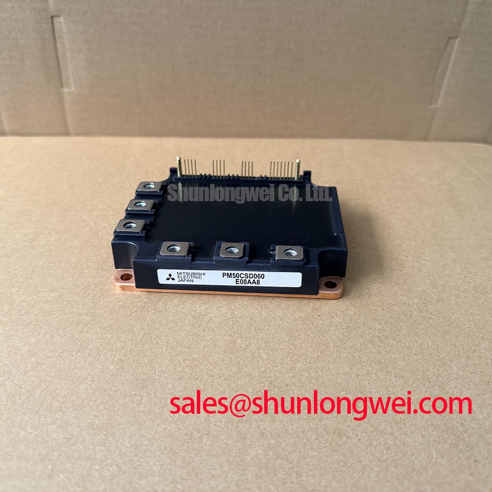
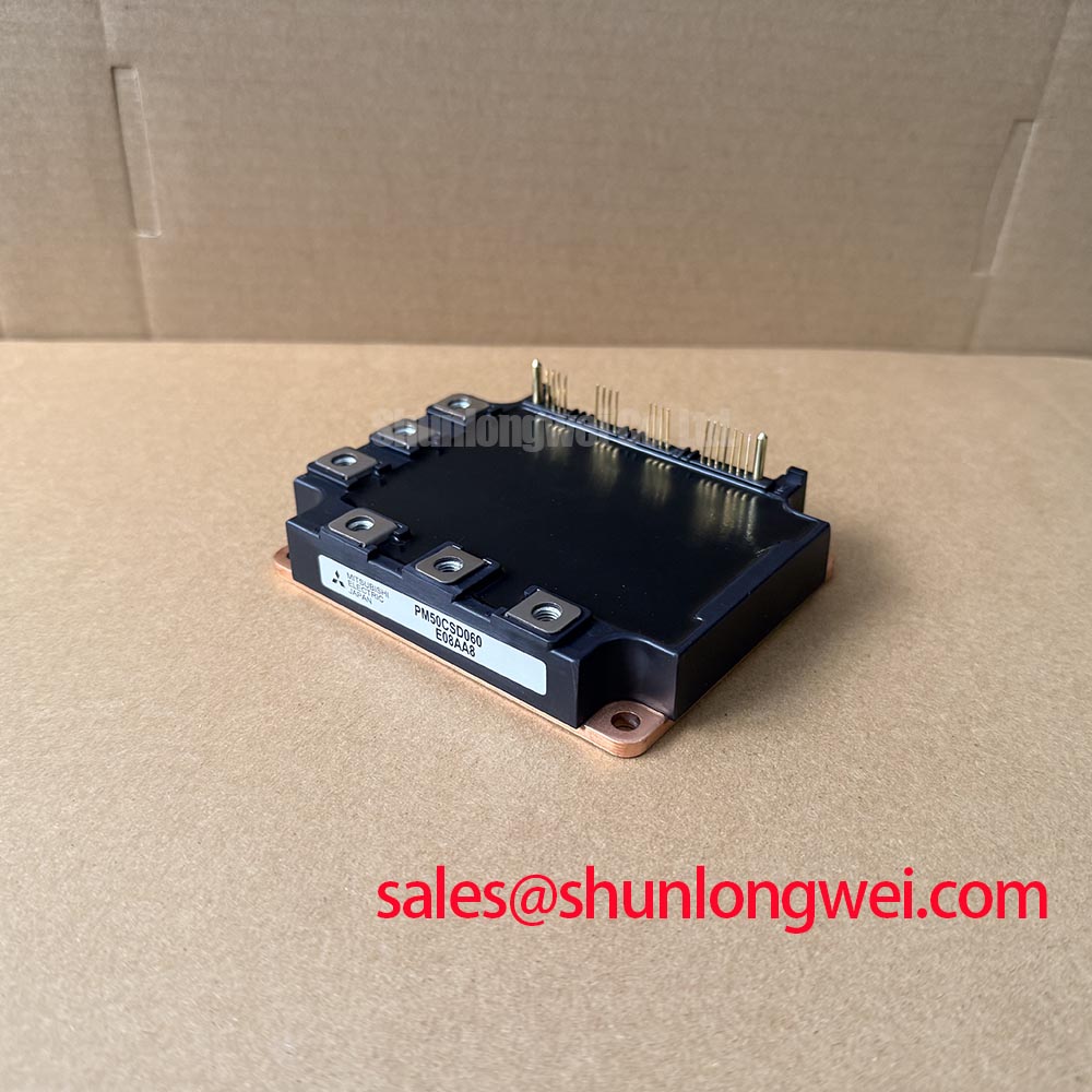
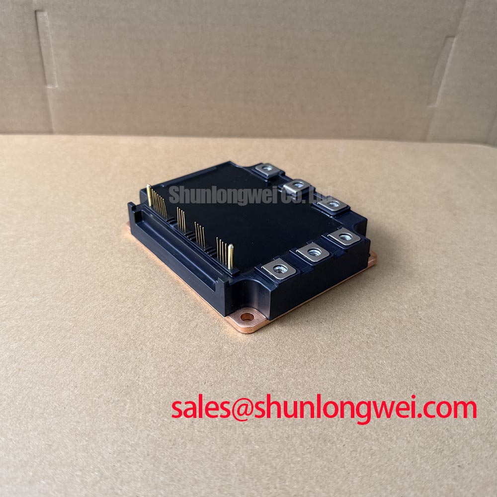
Before fitting the PM50CSD060, isolate the equipment, inspect the module terminals and baseplate contact area, then verify that the inverter control board has no conductive debris or moisture tracks near the gate-drive connections. This Mitsubishi Electric IPM is officially rated at 600 V VCES, 50 A IC, and 100 A peak collector current. Those limits define the device boundary; they do not establish the operating voltage, gate-drive amplitude, switching frequency, or protection delay for a specific servo drive.
In a high-dynamics multi-axis CNC or robotics servo inverter, rapid collector voltage transitions can couple through gate capacitances and disturb an IGBT that is intended to remain off. A dedicated active Miller clamp is a Design Consideration where the driver architecture supports it. The clamp should provide a low-impedance path between the off-state gate and its relevant emitter reference after the gate has discharged, while the complete driver loop is kept compact and referenced correctly. The purpose is to reduce unintended gate rise and the associated risk of cross-conduction during commutation.
The requested gate-driver polarity and bias range must be verified against the original inverter documentation and the actual driver IC limits. Although negative off-state gate bias is common in some industrial gate-drive arrangements, it is not an official PM50CSD060 parameter supplied here and must not be assumed as a module requirement. Engineers should capture gate-emitter voltage and collector-emitter voltage together during commissioning, using appropriate isolated measurement methods, to see whether a switching disturbance corresponds with a gate excursion or with another part of the power stage.
Layout is an Engineering Recommendation rather than a fixed module specification. Keep the gate-driver return path controlled, separate sensitive signal routing from high-current commutation conductors, and place local decoupling according to the driver and DC-link design. These practices help suppress inductive overshoot, but final peak-voltage margin must be verified during switching tests against the installed DC-link voltage and the equipment duty cycle.
For equipment repair, do not treat an intermittent overcurrent trip as proof of a defective power module. Check the gate-drive supply stability, interlock signals, connector seating, current-sensor path, and phase-to-phase wiring before replacing parts. Mitsubishi Electric's DIPIPM Bootstrap Circuit Design guidance is a useful external reference for reviewing bootstrap supply behavior and switching-node-dependent driver circuits, while the original machine documentation remains the governing source for this module installation.
Preventing Spurious Faults: Thermal Time Constants and Peak Junction Guidelines for PM50CSD060
The module's thermal limits must be interpreted with the manufacturer's specified junction, case-temperature, and cooling conditions. Its listed 125 W power dissipation is an official datasheet specification, but it must be interpreted with the manufacturer test conditions and the complete thermal path. It is not a universal power allowance for every heat sink, enclosure, switching pattern, or ambient temperature.
Pulsed servo loading needs a transient thermal review because mechanical acceleration and regenerative events can impose high current for short intervals. A multi-RC thermal model, where available from the applicable original documentation, represents heat movement from junction to case over time rather than treating temperature as an instant response. An Engineering Calculation can combine measured or estimated conduction and switching losses with the applicable transient thermal impedance to estimate peak junction temperature. The calculation is only credible when its pulse duration, repetition rate, case temperature, cooling condition, and waveform data reflect the real machine cycle.
Switching frequency between 2 kHz and 16 kHz changes the balance between switching loss, acoustic objectives, motor behavior, and cooling demand. This range is an integration condition, not an official PM50CSD060 switching-frequency rating. When integrating the module into a servo drive, designers should evaluate the loss profile at the selected frequency and verify temperature response across acceleration, holding, braking, and fault-recovery duty. A stable temperature during an unloaded bench run does not validate the same installation under repeated multi-axis motion.
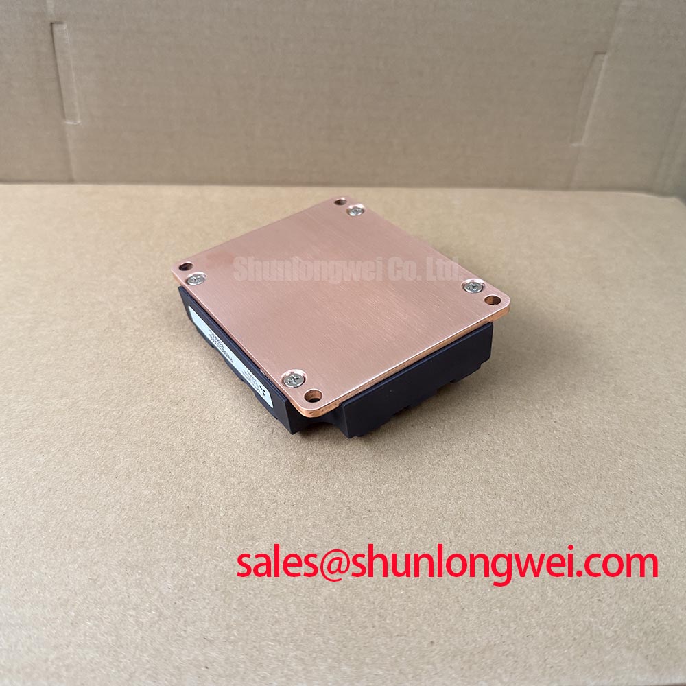
Inspect the heat sink and airflow route as part of routine preventive maintenance. Dust accumulation, blocked filters, aged thermal interface material, loose mounting hardware, and uneven baseplate contact can each increase thermal resistance. Where the original assembly specifies mounting hardware and torque, follow that documentation; no mounting torque is asserted here as a PM50CSD060 factory specification. Maintenance Note: Record heat-sink contact temperature trends and check that the cooling air path remains clear before attributing a thermal trip to the module.
Condensation control also belongs in the service review. A cabinet that cycles through low temperature and warm operation can develop moisture on boards, connectors, and insulation surfaces. Restore enclosure sealing, cabinet heating or ventilation arrangements, and drainage provisions according to the machine design before returning a repaired axis to service.
PM50CSD060 Operational Boundaries: Evaluating Isolated DC-DC Power Supply Sizing for High Limits
The module has an official isolation-voltage rating of 2500 V AC for 1 minute. This is a specified isolation test condition, not evidence that a complete converter has reinforced insulation above 5 kV, a defined common-mode transient immunity rating, or a particular system safety certification. Those properties depend on the isolated DC-DC converter, gate driver, printed-circuit board clearances, wiring, enclosure, and the end equipment's applicable requirements.
For a replacement or retrofit assessment, identify every gate-drive supply rail from the original schematic, then check actual no-load and switching behavior at the driver-side supply pins. The isolated supply must have adequate regulation and transient capability for the installed driver circuit and its switching duty. Supply dip, poorly referenced measurement equipment, or common-mode disturbance can produce an apparent drive anomaly without establishing a single root cause. Compare waveforms against a known-good axis where available and verify the protection logic state at the same time.
Isolation coordination is a Design Consideration. Maintain the intended physical separation between primary power conductors and low-voltage control circuits, keep high-voltage switching nodes away from sensitive feedback routes, and inspect board contamination that could compromise surface insulation. The system engineer should verify surge behavior, common-mode performance, and required clearances through the applicable equipment standards and test plan. Mitsubishi Electric's high-voltage power semiconductor information provides broader manufacturer context, but it does not replace the original documentation for this IPM application.
When a higher-current module family is being reviewed for a different repair design, CM100DY-12E can be compared as a separate component reference. It should not be treated as a drop-in substitute. Voltage class, topology, terminal arrangement, gate-drive requirements, thermal interface, control protection, and mechanical fit all require independent verification.
Field Diagnostics & Commissioning: High-Speed Fault Management: VCE Desaturation in PM50CSD060 Topologies
Start post-repair commissioning with the original controller's protection chain intact. Verify phase wiring, DC-link polarity, gate-drive connectors, current-feedback connections, command inhibit behavior, and emergency-stop circuitry before applying operating power. The PM50CSD060 is rated at 600 V, with a typical official VCE(sat) of 1.7 V, but the typical saturation-voltage figure is defined under manufacturer test conditions and cannot by itself diagnose an installed inverter.
Desaturation monitoring is commonly used in externally driven IGBT topologies to identify an abnormal collector-emitter condition while a device is commanded on. Whether it is present, how it is filtered, and how the controller reacts are system-level design choices. A two-stage soft turn-off approach can be considered where the driver and protection architecture support it, because abruptly interrupting fault current in an inductive path can create a damaging voltage transient. The final timing, current threshold, clamp method, and safe-operating validation must be determined from the original drive design and verified with suitable test equipment.
Do not assert a type-I or type-II short-circuit capability, a sub-10-microsecond response requirement, or a short-circuit safe-operating-area limit for this part without the applicable official module documentation. During fault investigation, use controlled power-up procedures and inspect the recorded fault history. A recurring desaturation event may indicate a gate-drive problem, motor-cable issue, phase short, feedback error, commutation disturbance, or control sequencing condition. Confirm the evidence with synchronized voltage, gate, and current measurements where the service procedure permits.
For CNC and robotics servo systems, commission one axis at a time where the machine procedure supports isolated-axis testing. Observe the module heat-sink condition and protection response during low-risk motion before validating higher dynamic loads. Keep the cabinet closed when the specified airflow path depends on it, and document any waveform or temperature difference between the repaired axis and a known-good channel for the next maintenance review.