Content last revised on October 29, 2026
Benchtop Waveform Tuning: Mitigating Switching Stress Through PCB Layout on PM50RLB120
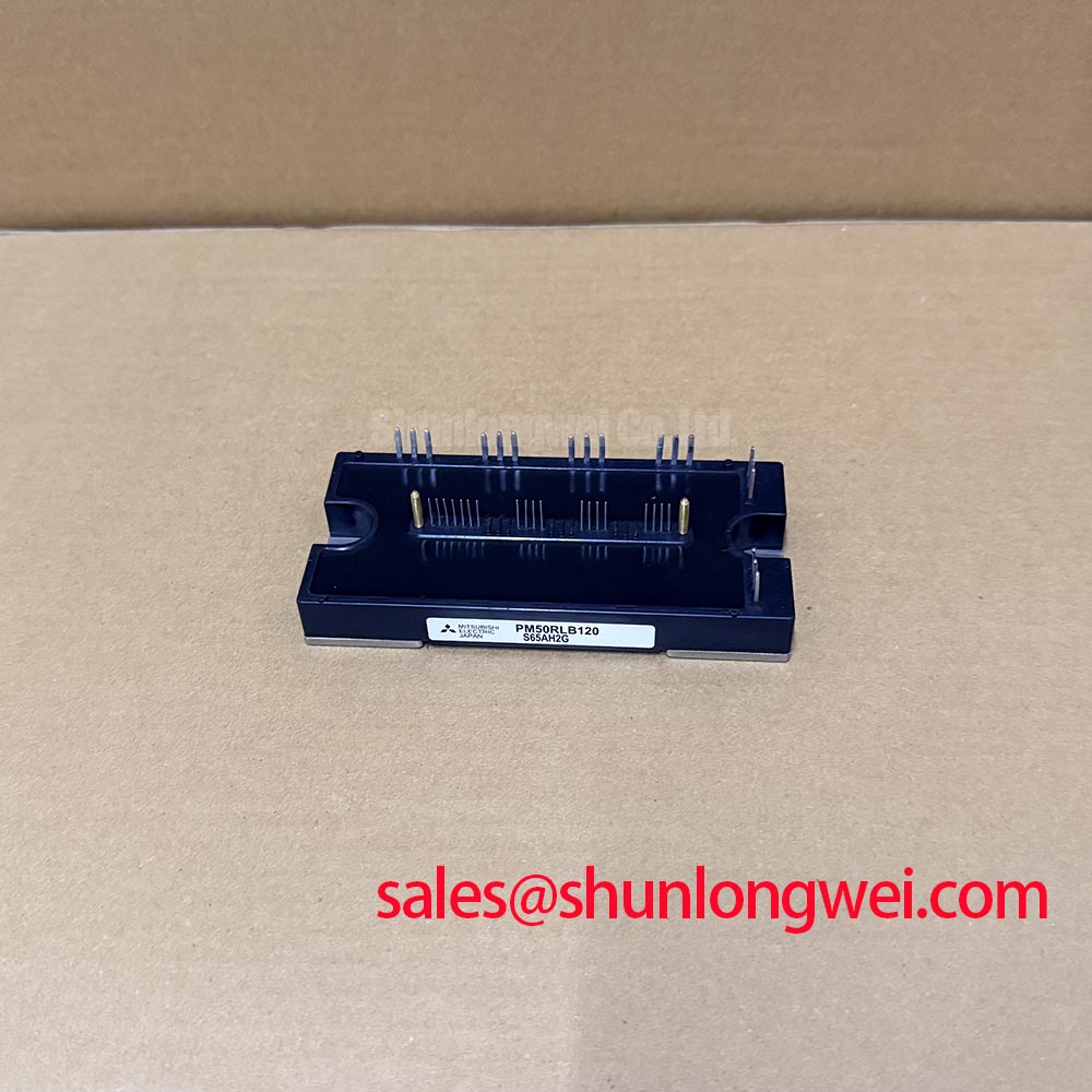
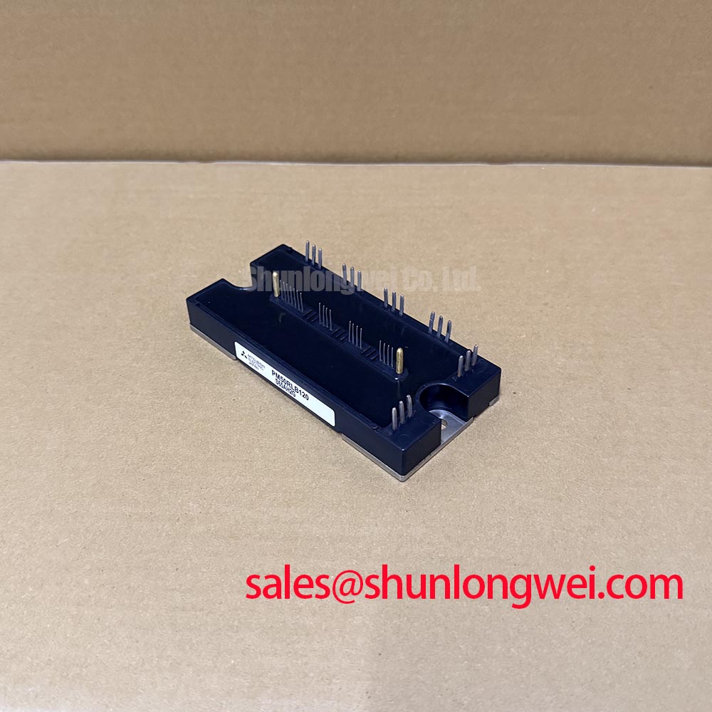
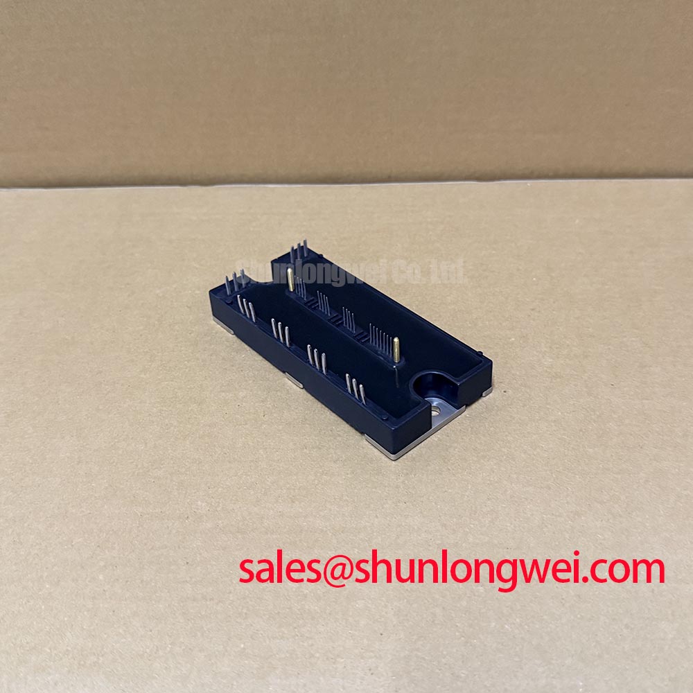
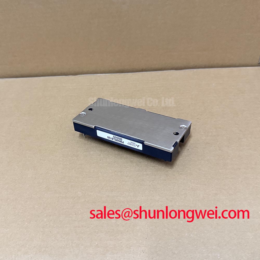
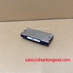
With the DC link isolated and verified discharged, compare cold resistance readings between the main power terminals before reconnecting the control board. Record probe polarity, isolate parallel circuit paths, and compare corresponding branches rather than judging the module from a single meter reading. The PM50RLB120 from Mitsubishi Electric is an IPM, or Intelligent Power Module, with voltage and current ratings of 1200 V and 50 A, subject to the manufacturer’s specified conditions.
Those electrical ratings establish the starting point for identification. A repair decision also depends on the terminal arrangement, control interface, protection behavior, and mechanical fit. Photograph the installed connections and retain the equipment schematic before removing the assembly. A low resistance reading can involve the surrounding circuit, while an apparently balanced set of readings cannot establish correct switching or protection operation.
Trace each control return to its designated module reference before changing PCB routing. Design Consideration: shared impedance between a sensitive control return and a high current switching path can disturb the voltage seen by the drive circuit. Keeping those paths appropriately separated reduces this coupling, but the separation must follow the actual terminal diagram.
For this IPM, identify the external control terminals and their reference connections before treating any terminal as an auxiliary emitter. A return carrying switching current should not become the reference for a logic measurement simply because it appears close on the board. Where the equipment provides separate control supply returns, preserve their intended connections through the connector and PCB rather than joining them at a convenient busbar fastening point.
During waveform checks, use a differential or isolated measurement arrangement appropriate to the switching node and measurement environment. Keep the probe connection compact, and repeat a suspicious measurement with a different probe position. A waveform that changes substantially when the measurement loop moves deserves investigation before it is attributed to the module. Compare command signals, local control supply behavior, and phase switching at the same operating condition.
Design Consideration: PCB symmetry is useful when it makes corresponding signal paths behave consistently, but visual symmetry alone does not establish electrical equivalence. Compare return paths, nearby switching copper, connector transitions, and the placement of isolation components. Review creepage along insulating surfaces separately from clearance through air. Required distances depend on the equipment insulation design, working voltage, pollution environment, and applicable product standard; the module voltage rating is not a PCB spacing rule.
When assessing commercial string inverter or microgrid energy storage equipment, engineers should compare the complete power stage interface before considering this module for a repair. The related PM150RLA120 provides a separate model for specification comparison, not evidence of interchangeability. Match circuit configuration, terminal positions, control requirements, mounting geometry, and thermal conditions before advancing either part through an equipment compatibility review.
Transient Dynamics & Electrical Design: Control Interface Integrity on PM50RLB120
Inspect the control supply and command waveforms at the module interface when switching transitions coincide with unexplained current spikes. Design Consideration: collector voltage transitions can couple current through gate capacitance, and shared circuit impedance can disturb the effective gate voltage. In an IPM, the relevant field checks begin at the accessible control interface because external command terminals are not interchangeable with the internal IGBT gates.
Active Miller clamping and negative gate bias are driver design techniques, but they are not installation instructions for this module. Apply only the supply and input conditions specified for the actual IPM interface. Adding a negative supply or an external clamp to a logic terminal would not reproduce a discrete IGBT gate drive circuit. At equipment level, examine control supply decoupling, isolation behavior, command integrity, and the timing relationship between complementary switching commands.
Confirm connector orientation from terminal identification rather than cable color. Check continuity between the harness and the intended control board nodes with power removed, then examine local supply behavior during a controlled switching test. A disturbance can originate in the supply, isolator, connector, return routing, or power stage. Comparing these signals together helps locate the disturbance without assigning every transient to a failed semiconductor.
Design Consideration: freewheel diode reverse recovery can influence commutation current, voltage ringing, and electromagnetic emissions. Recovery softness describes the shape of the reverse recovery current decay, but no numerical softness factor is assigned here to PM50RLB120. Engineers should assess observed recovery behavior under relevant current and temperature conditions, while also examining loop inductance and measurement bandwidth. A sharp waveform feature alone does not identify either a diode defect or an equipment EMC failure.
The Mitsubishi Electric motion control resources provide broader context for power device applications. They do not establish a particular internal chip structure for this model. For the equipment architecture, identify the rectifier, DC link, inverter, and any braking branch from the schematic. The separately listed PM50B6L1C060 can be reviewed during an associated module assessment, but its place in a complementary stage must follow its own circuit documentation rather than a presumed rectifier role.
Assembly Integrity & Layout Architecture: Preventing Terminal Overheating on PM50RLB120
Measure a suspect bolted connection with a four wire micro-ohmmeter after isolating the assembly and accounting for parallel paths. Design Consideration: the purpose is to distinguish joint resistance from lead resistance and surrounding circuit paths. Place the sense contacts so that the measurement covers the intended interface, record the connection temperature, and compare equivalent joints under consistent conditions. An arbitrary universal resistance threshold cannot establish acceptance for every terminal assembly.
Inspect mating surfaces for contamination, oxidation, uneven seating, and evidence of movement. Check whether the busbar bears flat against the terminal or pulls sideways when tightened. Mechanical stress from misaligned copper can remain after the fastener appears secure. Support the busbar and cable assembly so vibration and cable weight do not load the module terminal continuously. Use the specified fastening hardware and the applicable manufacturer tightening procedure.
Field Alert: Support the busbar during assembly and follow the specified tightening sequence and torque so that fastening does not twist the module terminals.
Thermal imaging becomes useful when the electrical load and cooling conditions are recorded with the image. Compare corresponding terminals, nearby conductors, and the surrounding thermal pattern rather than interpreting one bright area in isolation. Surface finish, reflections, viewing angle, and emissivity settings affect apparent temperature. A localized rise can justify further investigation of a joint, but it does not independently prove excessive contact resistance or an internal module fault.
Design Consideration: examine the cooling interface separately from the electrical joints. Check heat sink cleanliness, mounting surface condition, fastener seating, and the distribution of the specified thermal interface material. Uneven contact can change the thermal path even when terminal temperatures appear similar. The 50 A official current rating should be evaluated with the manufacturer’s stated thermal conditions and the equipment cooling arrangement before sustained loading.
Recheck creepage and clearance after assembly because displaced conductors, loose hardware, and residue can alter the physical insulation path. Inspect the route between power terminals and low voltage wiring, including beneath connectors and around busbar edges. For ongoing maintenance, record connection condition, comparative resistance readings, load, and thermal images in the same service record. This supports comparison over time without inventing a fixed inspection interval or a predicted operating life.
Transient Dynamics & Electrical Design: Assessing Overcurrent and Short Circuit Protection on PM50RLB120
Trace the equipment fault response from the module interface to the controller inhibit function before authorizing another powered test after an overcurrent trip. Design Consideration: effective protection includes fault recognition, signal transmission, command inhibition, and the resulting current decay. A controller log can confirm that a fault was reported, but it cannot by itself establish how quickly the semiconductor current stopped or what voltage appeared during turn-off.
A short circuit present when switching begins and a short circuit developing during conduction impose different transient conditions. These are commonly discussed as type I and type II events. Their evaluation must follow the device protection specification and the equipment test procedure. No universal short circuit duration, detection threshold, or safe operating area is assigned to PM50RLB120 from its voltage and current ratings alone.
Use controlled tests to observe the accessible fault signal, control supply, command inhibition, current, and switching voltage together. Check whether the controller maintains the required inhibit state and whether reset behavior follows the equipment sequence. Avoid repeatedly clearing an alarm while leaving its initiating condition unresolved. A fault indication can accompany supply disturbance, abnormal current, or other protection conditions; correlate the signal with measured behavior before choosing a repair action.
Design Consideration: controlled turn-off can reduce inductive voltage overshoot, while slower current interruption can increase semiconductor energy dissipation. Two stage soft turn-off therefore requires a driver architecture and validation procedure that support it. It should not be presented as an external adjustment available on every IPM. For this module, assess the specified protection behavior and the equipment response at accessible terminals, keeping peak voltage and fault energy within documented limits.
The Mitsubishi Electric Power Semiconductors & High-Power Modules resources provide the manufacturer context for device documentation. The related Precision Gate Drive Design discussion supports assessment of drive behavior and measurement methods without establishing a service life for this part. Before returning the repaired assembly to operation, verify that the fault response inhibits switching, the reset sequence behaves correctly, and controlled load testing shows acceptable current, voltage, and thermal behavior under the equipment’s approved acceptance procedure.