

Content last revised on October 8, 2026
PM50RSD120 Identification and Pre-Service Checks
Before disconnecting the PM50RSD120 from a stopped heavy-duty variable frequency AC motor drive, isolate every energy source, verify DC-link discharge with suitable test equipment, and photograph the power terminals and control connections. With the module electrically isolated, compare corresponding power-terminal measurements in both meter polarities; an unexpectedly low resistance warrants further investigation, not an immediate diagnosis of an internal semiconductor failure.
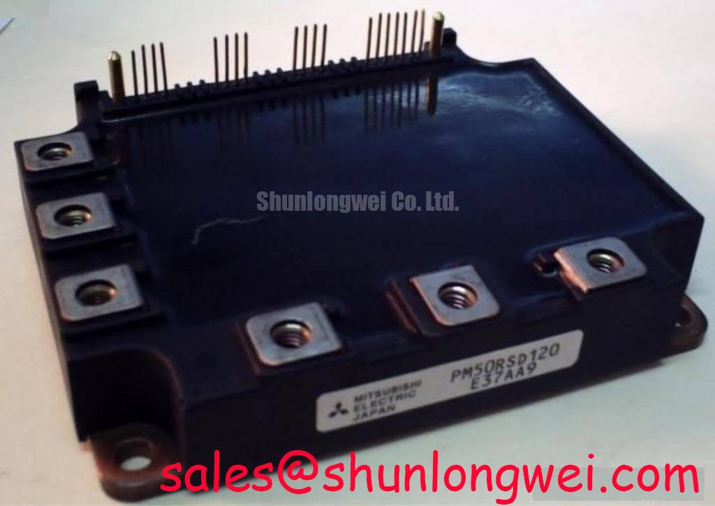
The Mitsubishi Electric PM50RSD120 is an IPM, or Intelligent Power Module, with the following official specifications. These identify the component’s electrical rating class and package category; they do not establish the allowable drive output, overload duration, switching frequency, or mounting procedure.
| Product characteristic | Value | Specification identity |
|---|---|---|
| Model | PM50RSD120 | Product identification |
| Manufacturer | Mitsubishi Electric | Manufacturer identification |
| Rated voltage | 1200 V | Official Specification |
| Rated current | 50 A | Official Specification |
| Package | Mitsubishi IPM Module | Official Specification |
PCB Symmetry Considerations for Dual IGBT Half-Bridge Switching Paths
Start with the drive schematic rather than assuming that two adjacent power terminals represent interchangeable switching paths. The PM50RSD120 package designation alone does not establish its complete internal topology, terminal assignments, or availability of an auxiliary emitter connection. When assessing paired half-bridge switching paths in the surrounding inverter, map each control reference, power conductor, and feedback connection against the original module documentation and equipment drawings before making continuity checks.
As a Design Consideration, comparable switching paths should have controlled return routing and comparable parasitic impedance. Shared high-current conductors can introduce voltage disturbances into control references during switching. Where the documented interface provides a separate control reference, preserve its intended routing rather than merging it casually into a power return. Do not add a supposed Kelvin emitter connection to this module without a verified terminal definition. An integrated driver interface must be treated differently from the exposed gate connections of a discrete IGBT module.
Inspect the PCB around the control connector for cracked solder joints, contamination, damaged insulating barriers, and altered return paths. Compare the affected channel with an equivalent working channel, but account for intentional schematic differences. During qualified energized testing, use probes suitable for the common-mode voltage and measurement location. An observed oscillation may involve probe coupling, drive-supply disturbances, control routing, or the power loop; checking those possibilities is more useful than assigning the symptom to a single component.
Clearance and creepage are also Design Considerations, not dimensions that can be inferred from the 1200 V rating. Required spacing depends on working voltage, insulation arrangement, pollution conditions, materials, and applicable equipment standards. Restore original insulating hardware and barriers. If a repair changes conductor placement or PCB geometry, the equipment designer should reassess the affected insulation distances rather than accept a generic spacing rule.
For motor-drive feedback analysis, the Clarke Transformation, also called the alpha-beta coordinate transformation, explains how phase-current measurements can be represented for control calculations. It does not establish the PM50RSD120 terminal map or protection behavior. Before attributing unequal phase currents to the power module, verify current-sensor polarity, signal integrity, and the controller’s phase mapping.
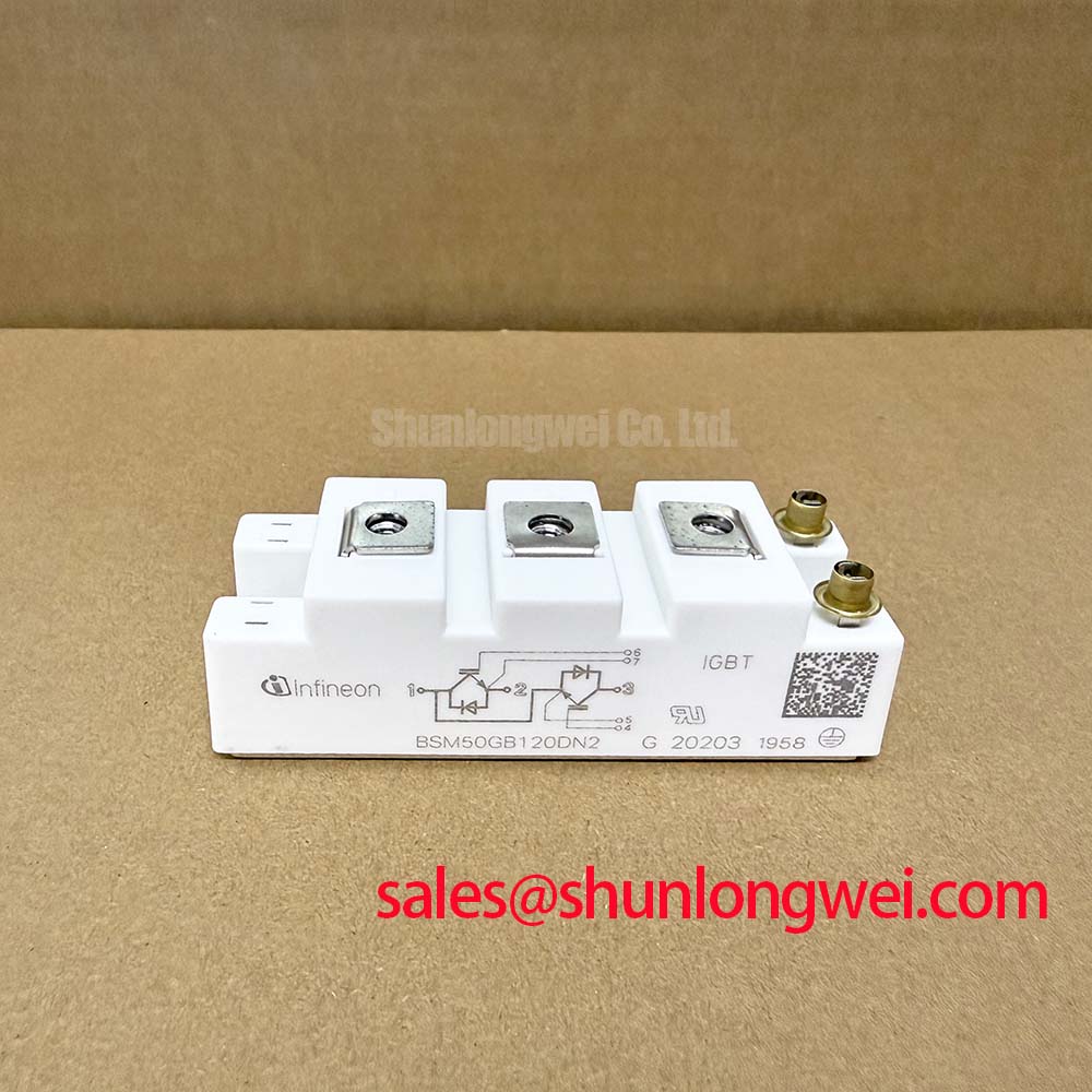
Replacement assessment should separate electrical rating comparisons from interface compatibility. The CM200DY-24E can be included in a broader power-module comparison, but it should not be treated as a drop-in replacement for the PM50RSD120. Compare topology, driver requirements, terminal geometry, protection provisions, and cooling arrangements using the respective documentation. A shared voltage class alone cannot establish interchangeability.
Dynamic Power Loss Dissipation and Multi-RC Thermal Ladder Representation
When a drive trips after repeated acceleration or sustained loading, record the operating condition before disturbing the cooling assembly. Useful evidence includes output-current history, switching settings, heatsink temperature, fan operation, and the interval between loading and shutdown. As a Design Consideration, these observations help distinguish a cooling-path problem from increased semiconductor losses or an unrelated protection event. The PM50RSD120’s 50 A rating is not an unconditional continuous-current allowance at every case temperature.
A multi-RC thermal model is useful only when its coefficients represent the relevant thermal path. Junction-to-case data describe a different boundary from junction-to-heatsink or junction-to-ambient data. A Foster network fitted to a transient curve should not be connected arbitrarily to another thermal network; a physically compatible model or an appropriate conversion is needed. Using coefficients borrowed from a similarly rated module can produce a plausible temperature trace without establishing a defensible PM50RSD120 junction-temperature estimate.
For an Engineering Calculation, a constant-power pulse produces a junction-temperature rise equal to pulse power multiplied by the applicable transient thermal impedance at that pulse duration. The calculation requires validated loss data, the correct thermal curve, and a defined case-temperature boundary. Repeated overloads require accounting for accumulated heat from preceding pulses. Without the manufacturer’s thermal characteristics and temperature limits, a numerical peak junction temperature or overload margin should not be assigned to this product.
At the bench, inspect the thermal interface for an uneven contact imprint, displaced compound, debris, and local discoloration. None of these observations alone proves excessive junction temperature, but they can identify conditions requiring correction. Thermal compound thickness must follow the module’s mounting guidance and the interface material’s application instructions. A generic film thickness is not an official PM50RSD120 specification, and additional compound should not be used to conceal a distorted heatsink surface.
Check the complete heat-removal path before returning the drive to load. Restricted airflow, fouled fins, a damaged fan, or a changed enclosure arrangement can affect cooling even when the module-to-heatsink interface appears acceptable. Where an assembly drawing specifies a tightening pattern, preserve it during reassembly and apply final torque with a calibrated tool. Do not infer a tightening value from package appearance or a nominal screw size alone.
The DC-link supply also belongs in this assessment. Check the equipment’s documented rectification stage, bus connections, and capacitor condition before interpreting inverter heating. If evaluating another power assembly such as SKIIP37AC12T4V1 elsewhere in the system, verify its actual topology and interface from its own documentation; the reference does not establish that it is a suitable front-end rectifier or a compatible companion to the PM50RSD120.
High-Speed Fault Management: V_CE(sat) Desaturation Sensing Circuitry
When the drive reports a power-stage fault, capture the fault history and determine whether the indication originated in the module interface, the controller, or an external sensing circuit. An IPM should not automatically be treated as a bare IGBT requiring a newly designed external desaturation circuit. Confirm the PM50RSD120’s documented control inputs, fault outputs, protection functions, and supply requirements before connecting test equipment or changing the surrounding circuitry.
As a Design Consideration, desaturation sensing monitors whether a conducting IGBT’s collector-emitter voltage departs from the expected conduction condition. Detection behavior depends on the sensing arrangement, switching transients, blanking interval, and protection threshold. These principles do not establish a detection time, voltage threshold, or short-circuit withstand duration for this model. A short-circuit safe operating limit must come from the applicable manufacturer specification, including its test conditions.
Type-I and type-II short-circuit descriptions distinguish different fault initiation conditions in power-switching analysis. They are not permission to apply a deliberate short circuit to a repaired drive. Qualification of fault interruption belongs in a controlled test arrangement with documented limits. For field repair, inspect the motor cable, output connections, insulation condition, and current-feedback path using the equipment manufacturer’s procedures before attempting an operational restart.
If the documented protection design includes controlled or staged turn-off, preserve that behavior. As a Design Consideration, rapid current interruption can increase inductive overvoltage, while prolonged interruption can increase device stress. The balance depends on the power loop and protection architecture. It cannot be reduced to an invented two-stage timing prescription for the PM50RSD120, and external circuitry should not bypass an integrated protection function.
Check the control supply and fault signal under the conditions specified by the equipment documentation. A fault that appears during acceleration may involve supply droop, load current, cooling, signal interference, or an actual power-stage defect. Compare measured waveforms with a known-good circuit where available, using suitable isolation and probing practices. The Field Engineer’s Handbook provides broader testing and failure-analysis context; model-specific acceptance limits must still come from the component and drive documentation.
Thermal Paste Degradation Prevention and Mechanical Clamping Torque Calibration
Before installing the replacement module, inspect the heatsink contact area under good lighting and remove residual interface material using a method compatible with both surfaces. Check for raised edges, embedded debris, damaged threads, and evidence that previous fasteners bottomed out before producing clamping force. As a Design Consideration, uneven contact can compromise heat transfer even when the mounting screws appear tight.
Apply the specified thermal interface material using its documented process and the module mounting instructions. Coverage, pressure, surface flatness, and material behavior all affect the resulting interface. Do not assign the PM50RSD120 an unsupported paste-thickness range or assume that all visible squeeze-out indicates correct assembly. A contact imprint can help assess distribution during an approved inspection procedure, but it is not a direct measurement of thermal resistance.
⚠️ Field Alert: Do not energize the drive until the documented mounting torque and tightening sequence have been verified and applied with a calibrated tool.
Use the prescribed fasteners, washers, and insulating parts, and confirm that their length matches the assembly drawing. Where staged or cross-pattern tightening is specified, follow that sequence without substituting an assumed torque. Do not attempt to compensate for baseplate or heatsink curvature with improvised shims, excess compound, or additional clamping force; resolve the mechanical condition against the approved mounting requirements.
Before reconnecting power, verify terminal placement, connector seating, cable support, and the absence of trapped conductors. Record the replacement identification, interface material, verified tightening settings, and inspection results. During the equipment’s approved restart procedure, observe fault status, phase-current behavior, and cooling performance at the prescribed test conditions, stopping for investigation if the measurements depart from the documented acceptance criteria.