Content last revised on September 22, 2026
PM600DSA060-4 Thermal-Electrical Optimization: Sizing Braking Resistors and Chopper Trans Practical Tuning
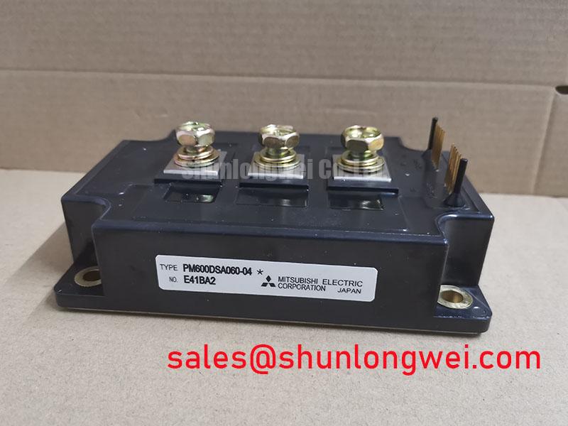
With the DC link discharged and isolated, first verify the inverter cabinet nameplate against the module’s 600 V VCES and 600 A continuous collector-current ratings before reconnecting any power or gate-drive harness. The PM600DSA060-4 from Mitsubishi Electric is an Intelligent Power Module specified with a typical collector-emitter saturation voltage of 1.8 V at 600 A and Tj = 25°C, switching operation up to 20 kHz, 2500 Vrms isolation voltage, and integrated SC, OC, OT, and UV lockout fault logic. These are Official Datasheet Specifications and define the electrical boundary that the surrounding inverter, brake circuit, cooling assembly, and protection scheme must respect.
| Official Specification | PM600DSA060-4 Rating |
|---|---|
| Manufacturer | Mitsubishi Electric |
| Collector-Emitter Voltage | 600 V |
| Continuous Collector Current | 600 A |
| Collector-Emitter Saturation Voltage | 1.8 V typical at 600 A, Tj = 25°C |
| Maximum Switching Frequency | Up to 20 kHz |
| Isolation Voltage | 2500 Vrms |
| Integrated Fault Logic | SC, OC, OT, UV lockout |
A decelerating motor returns mechanical energy to the DC link, so maintenance teams should begin brake-circuit investigation by logging DC-link behavior during the actual ramp-down sequence rather than judging the resistor from its exterior condition alone. In an inverter using the PM600DSA060-4, the braking path must absorb regenerated energy without allowing the DC link to approach the module’s 600 V VCES limit. The module voltage rating is an Official Datasheet Specification, while the brake-resistor value, pulse-energy capability, chopper switching threshold, and deceleration profile are system-determined parameters.
As a Design Consideration, braking-resistor selection starts with the energy returned by the driven load during each stop, the allowed stopping frequency, and the resistor’s ability to reject accumulated heat between events. A resistor that survives one hard stop may still run beyond its enclosure thermal capability after repetitive braking. Inspect the resistor mounting hardware, terminal insulation, airflow path, and evidence of local heat discoloration. Any measured rise in DC-link voltage should be assessed together with motor speed feedback, commanded ramp time, supply conditions, and the brake-control signal. One observation cannot isolate a single cause.
For installations using a separate braking transistor, engineers should verify that the transistor voltage capability, gate-drive reference, current sensing, snubber arrangement, and resistor connection geometry are coordinated with the DC-link layout. Keep the high-current loop compact to reduce parasitic inductance that can add turn-off overshoot. Peak voltage must be measured under the highest relevant operating current and switching conditions, then compared with the available margin to the 600 V module rating. This is an Engineering Recommendation, not a fixed layout prescription for this model.
Long conductors between the brake resistor and chopper can create unwanted inductive behavior during rapid current interruption. Route brake wiring away from low-level gate-drive and feedback wiring, use suitably rated insulation and terminal spacing for the cabinet voltage, and check that cable support prevents repeated mechanical loading at live terminals. A resistor enclosure also needs a clear thermal path so heat does not migrate into the control electronics or nearby electrolytic capacitors.
⚠️ Maintenance Note: Isolate stored energy and verify the DC link is discharged before tightening brake-circuit terminals or removing any inverter connection.
Where an inverter topology includes an upstream rectifier or related power stage, the SKIIP37AC12T4V1 can be reviewed as a separate system-level device reference. It is not a declared substitute for the PM600DSA060-4; compatibility depends on the original circuit topology, control interface, voltage class, thermal arrangement, and protection coordination.
PM600DSA060-4 Thermal-Electrical Optimization: Evaluating Thermal Capacitance vs Heat Sink Practical Tuning
During scheduled service, remove accumulated dust from the heatsink fins and confirm that the cooling path is not bypassing air around clogged sections. The PM600DSA060-4 has a typical 1.8 V VCE(sat) at the stated 600 A and Tj = 25°C test condition, but this value alone is not a complete loss model for a working inverter. Conduction loss changes with current and junction temperature, while switching loss also depends on system voltage, current, gate-drive behavior, commutation conditions, and switching frequency. The official maximum switching-frequency statement of up to 20 kHz should be treated as a product capability boundary, not as proof that every application is thermally acceptable at that frequency.
Transient thermal analysis is particularly important when the load produces repeated short overloads. A semiconductor junction does not immediately reach the same temperature as the heatsink because the thermal path stores and releases heat over time. Engineers commonly represent this response with a multi-RC transient thermal network, using the applicable manufacturer thermal-impedance information, the measured or calculated loss pulse, pulse duration, repetition pattern, and measured case temperature. The result is an Engineering Calculation that estimates junction-temperature excursion. A numerical peak junction-temperature conclusion should not be assigned here because the required transient thermal curves, mounting interface data, and mission profile have not been specified.
The practical distinction is important. A large heatsink supports steady heat rejection, while thermal capacitance in the module and mounting stack influences how quickly the junction responds to a pulse. If overload alarms occur only after repeated acceleration cycles, inspect both the cooling path and the duty profile. If a trip appears during a single severe event, capture current, DC-link voltage, gate command, protection output, and case temperature trend where safely possible. This evidence separates a likely cooling limitation from a current transient, a control timing issue, or a supply-side disturbance.
Thermal interface material must cover the contact area consistently, without debris, hardened residue, or uneven clamping that creates local thermal resistance. The mounting torque, fastener sequence, interface material thickness, and any spring hardware should follow the original equipment documentation or the applicable module mounting documentation. Do not infer a torque setting from another package family. After maintenance, compare heatsink temperature distribution and cooling-air discharge behavior with a known healthy unit operating under a similar load.
High-speed semiconductor-fuse coordination should be verified against the fuse manufacturer’s time-current and I²t information, the available fault current, the DC-link source characteristics, and the protected device’s published surge and short-circuit capability. The PM600DSA060-4 includes SC and OC fault logic as an Official Datasheet Specification, but that does not remove the need for coordinated external fault isolation. Protection channels have different response paths and energy limits. The system engineer should validate the complete clearing sequence under controlled conditions rather than assuming that a fuse or internal shutdown acts as a universal protection layer.
For maintenance personnel developing a thermal inspection routine, monitor contact-temperature trends, fan condition, filter loading, heatsink cleanliness, and signs of moisture or condensation around power terminals. A cool ambient room does not automatically prove that the semiconductor case or interface is operating within thermal limits. Temperature should be interpreted with electrical loading, airflow condition, and the recorded operating cycle.
PM600DSA060-4 Circuit Protection & Reliability: Calibrating Multi-Module Parallel Current Sharing
Before approving parallel operation, compare the complete current paths rather than comparing nameplate current ratings alone. The PM600DSA060-4 is rated at 600 A continuous collector current, but use of multiple modules in parallel requires electrical symmetry, matched thermal conditions, coordinated protection behavior, and validation on the actual inverter assembly. Parallel current sharing is a system design exercise and cannot be confirmed from a single module’s current rating.
At steady state, IGBT conduction behavior can assist current balance because VCE(sat) typically changes with junction temperature in a manner that can support redistribution under certain operating conditions. This is a Design Consideration, not an assurance of equal sharing. Static balance still depends on module variation, busbar resistance, terminal contact quality, heatsink flatness, airflow distribution, and differences in local temperature. Current probes or calibrated shunts should be used to compare branches while the inverter runs through representative operating points.
Dynamic sharing is often more sensitive than static sharing. Unequal gate-loop length, unequal emitter return routing, different drive-output impedance, and different gate-command timing can cause one branch to switch before another. That branch may carry disproportionate switching stress even if the measured low-frequency current split appears satisfactory. Keep corresponding power and gate paths geometrically consistent wherever the system layout permits, and inspect every gate-drive connection after vibration service or cabinet repair. Oscilloscope captures should compare collector-emitter waveform behavior and branch current during both turn-on and turn-off.
The integrated SC, OC, OT, and UV lockout logic should be evaluated as part of the full protection chain. A fault report could arise from a genuine load event, a gate-drive supply disturbance, a sensing path issue, an overtemperature condition, or an interaction between several factors. The maintenance sequence should retain fault history, inspect connector retention, verify drive-supply stability under switching load, and compare the affected phase with a known healthy phase before replacing surrounding assemblies.
When reviewing lower-current equipment or a different inverter architecture, the CM100DY-12E is available as a neutral comparison reference. Its suitability must be confirmed from its own official ratings, circuit configuration, physical mounting requirements, thermal design, and drive arrangement. It should not be treated as a direct replacement based on product family naming or a superficial current comparison.
Mechanical consistency matters as much as electrical symmetry. Recheck busbar seating, terminal clamping, and cooling-interface pressure after any cabinet movement, transport event, or major thermal cycling period. Loose joints can alter both resistance and local heating, while excess force can damage terminals or distort the mating interface. If the inverter is located in a high-vibration environment, the service schedule should include terminal-security inspection according to the equipment manufacturer’s maintenance procedure.
Transient Dynamics & Electrical Design: DC-Bus Operating Voltage Headroom Derating on PM600DSA060-4
Measure DC-bus voltage directly at the inverter under representative switching and regeneration conditions, then compare the observed waveform with the module’s Official Datasheet Specification of 600 V VCES. A static multimeter reading is not sufficient to reveal switching overshoot, cable-reflection effects, or braking transients. The measurement method must have suitable bandwidth, probe rating, isolation practice, and connection geometry so that the recorded waveform is meaningful and safe.
DC-bus headroom is consumed by the nominal supply voltage, regeneration, commutation behavior, stray inductance, and reflections from long motor cables. A long motor cable can return a reflected wave toward the inverter, potentially increasing voltage stress at the motor terminals and affecting the switching environment. Designers should assess cable length, motor insulation requirements, output filtering, cable routing, and measured waveform behavior as a complete installation. Filter selection and any switching-speed adjustment must be validated against motor performance, EMI requirements for the complete equipment, thermal load, and actual peak voltage. The PM600DSA060-4 itself should not be represented as independently compliant with system-level EMC standards.
Gate-drive dead time also requires verification at the assembled inverter. Its purpose is to prevent unintended simultaneous conduction in a switching leg, yet an excessive value can affect waveform quality and load current behavior. The correct setting depends on the driver, power-stage propagation delay, current direction, operating temperature, and measured switching response. Use the original control documentation and confirm behavior with instrumented tests rather than applying a universal timing value.
The specified 2500 Vrms isolation voltage identifies the module’s official isolation rating. Installation-level insulation reliability remains dependent on cabinet clearance, creepage, contamination level, humidity, connector selection, busbar insulation, and the condition of protective covers. For systems exposed to damp or condensing conditions, inspect seals, cabinet heaters where fitted, drainage paths, and contamination around high-voltage surfaces. Do not energize equipment with visible moisture near power terminals or control connectors.
Altitude and cosmic-ray-related single-event behavior are high-risk reliability subjects that require device-specific manufacturer characterization and an application-specific operating profile. No failure-in-time rate, single-event burnout probability, or altitude derating figure should be inferred from the 600 V rating alone. As a Design Consideration, applications installed at elevated altitude should have their actual DC-bus waveform, environmental conditions, insulation coordination, and manufacturer guidance reviewed by the responsible system engineer before operating limits are established.
For structured troubleshooting of gate-drive routing, thermal paths, DC-link layout, protection interactions, and switching measurements, consult IGBT Design & Integration. Mitsubishi Electric also provides broader power-semiconductor context through its Power Modules and SBDs information and a useful reference on bootstrap circuit design. These references support system-level evaluation and do not replace verification against the original PM600DSA060-4 equipment documentation.