
Content last revised on September 10, 2026
Output Sinusoidal Filter vs dv/dt Reactor Selection for Remote Motor Leads
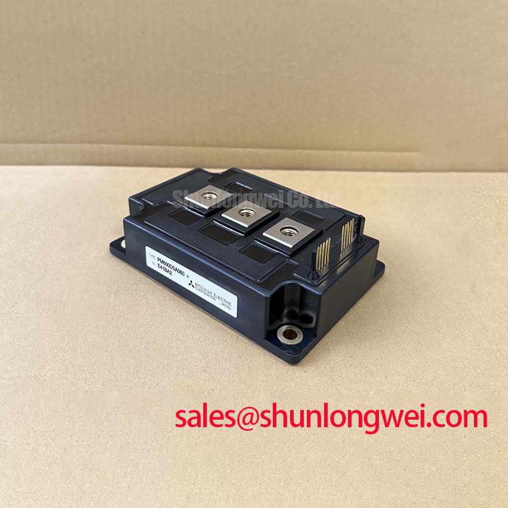
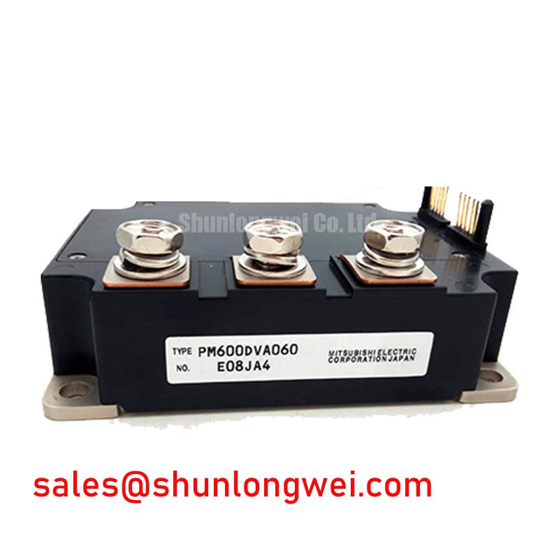
In locomotive propulsion bays and high-speed rail traction converter cabinets, feeding traction induction motors through long shielded cable runs spanning 30 to 100 meters creates severe transmission line impedance mismatches. The high-speed switching transitions of the PM600DVA060 dual Intelligent Power Module (IPM)—which integrates dual 600V, 600A (Official Datasheet Specification) IGBT switches with matched high-voltage gate drivers—generate steep output voltage transients. Because the characteristic impedance of the traction cable exceeds the characteristic surge impedance of the motor stator windings, traveling voltage waves undergo complete reflection at the machine terminals. Without mitigation, this reflection phenomenon doubles the instantaneous voltage at the motor leads, driving peak terminal voltages well beyond standard phase-to-phase insulation ratings and accelerating partial discharge breakdown in motor slot insulation.
Mitigating these transmission line reflection spikes requires choosing between a series dv/dt reactor and a complete LC sinusoidal filter. A standard dv/dt choke, placed adjacent to the converter cabinet output busbars, inserts series inductance that slows the voltage rate-of-rise to less than 500 V/µs. This suppression attenuates high-frequency ringdown without adding excessive voltage drop across the fundamental traction frequency. In contrast, full LC sinusoidal filters strip away switching harmonics entirely, supplying pure sinusoidal line-to-line voltages to the motor. While sinusoidal filters eliminate acoustic motor noise, bearing currents, and reflected wave doubling, they introduce bulk, weight, and capacitive reactive currents that reduce available inverter current margins during maximum tractive effort on steep gradients.
When selecting peripheral power stages or designing multi-tier auxiliary drives alongside the main traction line, engineers often evaluate complementary single-switch modules such as the CM400HA-12E to balance intermediate DC-link decoupling, auxiliary filter charging, or discrete phase legs. The high-voltage power routing inside the cabinet must adhere to strict geometric isolation: maintain a minimum of 12.5 mm creepage and 8.0 mm clearance distances between the uninsulated high-voltage AC busbars and chassis ground to avoid flashover under ionized or humid air conditions. Suppressing incoming line transients also requires placing high-energy metal-oxide varistor (MOV) networks directly across the intermediate DC bus terminals to clamp inductive back-EMF surges generated during emergency mechanical brake trips.
| Parameter / Metric | Pure dv/dt Output Reactor | Full LC Sinusoidal Filter |
|---|---|---|
| dv/dt Reduction Capability | Limits edge transitions to 300–500 V/µs | Reduces edge transitions to < 50 V/µs (near sine) |
| Peak Terminal Voltage (at 50m cable) | Attenuates reflection to ~1.3 × VDC | Eliminates reflection (≤ 1.05 × VDC) |
| Enclosure Mass & Footprint Impact | Low to moderate (compact iron/ferrite core) | High (requires large inductor bank & capacitors) |
| Motor Bearing Current Mitigation | Partial reduction of capacitive EDM currents | Near-total elimination of common-mode bearing currents |
Negative Gate Bias vs Active Miller Clamping in Fast-Switching Half-Bridges
Operating high-current half-bridge topologies at dynamic traction switching frequencies exposes the inactive, lower-switch gate to extreme capacitive displacement currents. When the opposing upper IGBT turns on rapidly, a sharp positive dv/dt appears across the collector-emitter terminals of the lower switch. This high dv/dt pushes displacement current through the internal gate-collector Miller capacitance (Cgc). If the gate driver output impedance is insufficient to drain this current, charge accumulates on the gate-emitter capacitance (Cge), lifting the gate voltage above the threshold level and causing instantaneous shoot-through across the 600V DC rail. The PM600DVA060 counters this through an integrated, matched gate drive network powered by a dedicated nominal control supply voltage of 15V (Official Datasheet Specification).
The internal driver circuitry of the IPM incorporates active protective clamping that shunts parasitic Miller current directly to the control emitter rail during high-voltage transients. This internal integration removes the need for an external negative gate turn-off rail (-5V to -15V), simplifying isolated secondary auxiliary power supply architectures. However, maintaining reliable operation requires isolating control power rails with robust common-mode transient immunity (CMTI). Optocouplers or digital magnetic isolators feeding the module’s control inputs must feature a certified CMTI rating exceeding 25 kV/µs to prevent false logic triggering during high-current commutations. When designing auxiliary low-voltage bootstrap circuits for related drive sub-assemblies, consult the Mitsubishi DIPIPM™ Bootstrap Circuit Design application note for isolation and charge replenishment layout guidelines.
⚠️ Maintenance Note: Thermal resistance degradation between the module baseplate and the liquid-cooled heatsink is a primary cause of latent semiconductor failure. During routine converter overhaul cycles (recommended every 24 to 36 months in transit environments), wipe away dried, oxidized silicone compound using an approved solvent cleaner. Apply a homogeneous layer of high-conductivity, non-curing thermal interface material (TIM) at a controlled wet thickness of 50 to 80 µm using a precision notched squeegee. Fasten the M5 mounting bolts in a diagonal cross-pattern sequence: pre-torque all bolts to 1.0 N·m to distribute the grease evenly, pause for 15 minutes to allow mechanical relaxation, and then apply a final torque within 2.5 to 3.5 N·m (Design Consideration based on M5 baseplate mechanical guidelines). Always handle loose control wiring and open gate terminals in compliance with Electrostatic Discharge (ESD) Protection Models (HBM, CDM, MM) to safeguard internal sensitive logic gates against catastrophic gate oxide rupture.
Thermal Time Constants (tau_i) and Peak Junction Temperature Margin Calculation
Heavy freight locomotives and high-speed traction units operate under severe cyclic loading, including full-throttle acceleration out of rail yards, regenerative braking descents, and wheel-slip recovery transients. These dynamic bursts subject the internal IGBT dies and antiparallel free-wheeling diodes to pulsed power surges that challenge the continuous thermal dissipation capacity of the cooling loop. The PM600DVA060 is engineered to withstand short-circuit conditions for a minimum short-circuit withstand time (tsc) of 10 µs (Official Datasheet Specification) while maintaining full electrical isolation across a certified isolation voltage rating (Viso) of 2500 Vrms (Official Datasheet Specification).
Calculating peak internal junction temperature during multi-second tractive effort surges requires modeling the transient thermal impedance Zth(j-c) as a multi-stage Foster or Cauer RC ladder network. The thermal time constant of the silicon die is short (typically in the 1 to 10 millisecond range), meaning the die junction tracks instantaneous electrical power spikes almost immediately. The copper baseplate presents a much longer thermal time constant (typically 1 to 3 seconds), acting as an integrated thermal buffer that absorbs brief power overloads before heat flows into the liquid cooling plate. By calculating the convolution of dynamic switching and conduction losses against the multi-term exponential thermal model, plant engineers can confirm that the instantaneous peak junction temperature remains safely within the maximum junction rating of 150°C (Official Datasheet Specification), while keeping the continuous baseplate case temperature strictly below 100°C (Official Datasheet Specification).
For in-depth diagnostic procedures on measuring thermal impedance shifts, structural voiding in solder layers, and monitoring thermal degradation over extended operational life, review the detailed testing methodologies published in the Field Engineer’s Handbook. Plant maintenance crews should perform calibrated thermal imaging scans through optical inspection ports on the inverter bay during annual dynamometer load bank testing. A steady-state temperature differential exceeding 15°C between adjacent identical IPM modules running under balanced phase currents serves as an early indicator of localized coolant passage scaling, pump cavitation, or thermal grease pump-out.
Thermal Cycling Margins of Internal Braking IGBTs under Repetitive Stop-Start Duty
Commuter trains and heavy freight locomotives encounter thousands of stop-start cycles each month, transferring vast amounts of kinetic energy back into the traction converter during deceleration. When the overhead catenary or third rail is non-receptive (unable to absorb returned regenerative energy due to substation diode isolation or lack of adjacent absorbing trains), the intermediate DC-link voltage rises rapidly. The traction control unit must instantly fire the dynamic braking chopper circuit to dump excess energy into an onboard, roof-mounted ballast resistor grid.
The repetitive pulse-loading of the dynamic brake chopper switch creates steep thermal cycles (ΔTj) within the semiconductor package. Each braking event causes the silicon die, the solder layer, and the copper baseplate to expand and contract at different rates due to their mismatched coefficients of thermal expansion (CTE). Over extended operating hours, this cyclic thermomechanical stress drives micro-crack propagation across the die-attach solder interface, raising the thermal resistance Rth(j-c) and causing bond wire heel cracking at the silicon surface. Ensuring operational longevity demands that the thermal surge profile of the braking chopper remains well below critical fatigue limits.
For auxiliary traction sub-systems, dynamic railcar heating, or lower-power distributed converter tiers requiring lower current handling, engineers often specify smaller-footprint modules such as the CM15MD-12H to optimize space and thermal balance across auxiliary power cabinets. Regardless of system size, ensuring reliable braking operation requires pairing the dynamic brake semiconductor with robust fast-recovery freewheeling diodes and passive snubbers to safely suppress the high inductive kickback generated by the long wiring runs leading to the roof resistor banks.
💡 Pro Tip: During quarterly plant preventative maintenance inspections, measure the DC electrical contact resistance across all main power terminal connections (P, N, U, V, W, and Brake terminals) using a calibrated four-wire Kelvin micro-ohmmeter. Any terminal showing a contact resistance greater than 50 micro-ohms should be disassembled, inspected for galvanic corrosion or plating wear, cleaned, and retorqued. Loose high-current busbar connections generate localized resistive heating that conducts straight through the main terminal studs into the IPM internal substrate, causing premature thermal trip faults or solder reflow failure under peak tractive load.