

Content last revised on September 16, 2026
PM600DSA060 Identification and Incoming Inspection
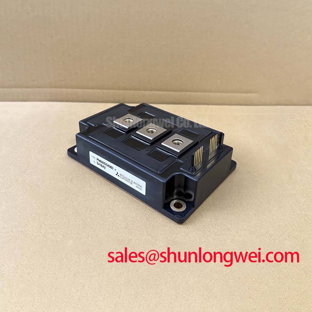
With the converter isolated, first compare the terminal markings, case condition, and cold-state junction readings of the installed PM600DSA060 against the original equipment documentation before any gate-drive connection is restored. This Mitsubishi Electric power module carries official ratings of 600 V VCES, 600 A DC collector current, 1200 A peak collector current, and 1730 W collector dissipation per element. These ratings define the device identity and electrical boundary; they do not replace verification of the surrounding bus voltage, protection hardware, cooling path, or driver timing in the host converter.
For incoming inspection, use the meter diode function only after confirming the module is disconnected from the DC link, gate-drive boards, snubbers, and parallel paths. Record the observed polarity and forward junction behavior between the labelled power terminals, then compare it with a known-good assembly or the original module documentation. A reading affected by external circuitry is not evidence of an internal module condition. The specified operating junction-temperature range is −20 to +150 °C, while the official isolation rating is 2500 V AC at 60 Hz for 1 minute; neither figure authorizes a live insulation test procedure without the equipment maker’s safety process.
💡 Bench Tip: Keep gate and auxiliary terminals protected from electrostatic discharge, and preserve a written cold-state baseline before reinstalling the module so later checks are compared with the same test leads, polarity, and disconnected circuit condition.
| Official Datasheet Specification | Rating or Value |
|---|---|
| Collector-emitter voltage, VCES | 600 V |
| DC collector current, IC | 600 A |
| Peak collector current, ICP | 1200 A |
| Collector dissipation, per element | 1730 W |
| Junction temperature, TJ | −20 to +150 °C |
| Isolation voltage, VISO | 2500 V AC, 60 Hz, 1 minute |
Transient Dynamics and Electrical Design for PM600DSA060 Hard-Switching Events
A hard-switching investigation should begin at the physical commutation loop rather than at the replacement module. Probe the DC-link voltage locally, observe collector-emitter behavior with properly rated differential instrumentation, and correlate the waveform with the driver command and fault signal. During turn-off, the peak device stress follows the familiar relationship in which DC-link voltage is increased by stray inductance multiplied by current slew rate. This is an engineering principle, not an official peak-voltage rating for the PM600DSA060. The system engineer must measure the actual peak margin against the 600 V VCES boundary in the completed equipment.
In a wind turbine full-scale converter or another high-energy drive cabinet, a failed braking path, depleted DC-link capacitors, damaged laminated connections, or changed gate-drive behavior can each alter the transient signature. Avoid treating a ringing waveform as proof of one isolated fault. Check whether the waveform changes when measured at different points, inspect busbar and capacitor hardware for disturbed contact surfaces, and confirm that the probe connection itself is not creating an exaggerated loop.
Short-circuit protection is a driver and system function, not an officially stated feature of this module. Type I and Type II short-circuit events have different initiating conditions, and a desaturation or collector-emitter monitoring circuit must be evaluated against the driver’s documented response characteristics and the converter’s measured energy conditions. Two-stage soft turn-off is commonly evaluated as a Design Consideration because it can reduce the severity of inductive overvoltage after a fault decision. Its timing, gate discharge path, and clamp behavior must be established by the complete protection design and validated under controlled test conditions. No universal detection interval should be transferred from another module or another converter cabinet.
Clearance and creepage around live terminals are also system-level insulation decisions. They depend on the enclosure, pollution environment, bus voltage, conductor geometry, altitude, and applicable equipment standard. The 2500 V AC isolation specification identifies the module’s stated isolation test rating, while external terminal spacing and barriers still require assessment at the assembly level. Before energizing a repaired converter, inspect for conductive debris, loose bus hardware, damaged insulating sheets, and cable strain that could compromise those external clearances.
For a structured measurement sequence covering isolation checks, cold-state comparisons, and waveform-led fault isolation, the Field Engineer’s Handbook provides a useful reference point for organizing the work around observable evidence rather than assumptions.
Planar Symmetrical Busbar Geometry and DC-Link Control Around PM600DSA060
The PM600DSA060 should be installed into the existing power-loop geometry only after confirming that its terminal arrangement and mounting interface match the original assembly documentation. Do not infer pin function or connection order from the part number. A planar, closely coupled positive and negative bus arrangement is often assessed as a Design Consideration because minimizing loop area helps suppress turn-off overshoot and ringing. The required residual inductance, snubber value, capacitor placement, and permitted switching rate are determined by the actual converter topology, voltage, current waveform, and protection response.
Where a DC-link capacitor bank connects to the module, inspect the shortest current-return path and the condition of all contact faces. Oxide, uneven clamping force, incorrect hardware stack-up, or a displaced capacitor interconnect can introduce resistance and inductance that are not visible in a schematic. During troubleshooting, compare switching waveforms from the repaired phase leg with a known-good phase where the equipment architecture allows it. A difference may indicate a bus-layout, driver, snubber, or measurement issue and should be resolved through targeted checks rather than a single-cause diagnosis.
Regenerative braking choppers and high-power braking resistors deserve attention because they determine where excess mechanical energy is directed when the DC link rises. The PM600DSA060 official ratings establish only the module’s stated device limits. Resistor pulse capability, chopper duty, thermal protection, cable routing, and fault handling belong to the converter-level design. When a braking event produces unexpected DC-link movement, verify command logic, resistor continuity, thermal switches, contactor status, and the recorded converter fault sequence before attributing the event to the power module.
Desaturation monitoring can be useful when the driver architecture supports it, but the threshold network and blanking behavior must be validated against normal conduction conditions and measured switching noise. A protection circuit that reacts to a transient generated by its own sensing loop can cause nuisance trips; a circuit that responds too slowly can expose the semiconductor to excessive fault energy. Keep the sensing route separated from high-current commutation conductors where practical, use the original equipment’s defined connection method, and confirm behavior on a controlled test bench.
Engineers comparing current class, voltage class, or circuit architecture can use CM100DY-12E as a separate reference model. It is not a drop-in substitute for the PM600DSA060. Electrical ratings, terminal layout, thermal interface, gate-drive requirements, protection coordination, and mechanical fit must all be verified from the relevant original documentation.
PM600DSA060 Thermal-Electrical Integration and Gate Return Routing
The published 1730 W per element collector dissipation rating must be read as an official device rating, not as a usable continuous heat-removal allowance for an installed cabinet. Actual thermal performance depends on conduction loss, switching loss, duty cycle, heatsink condition, coolant or airflow performance, interface material, mounting pressure, and temperature distribution across the assembly. For a repair assessment, inspect the heatsink mating surface for scoring, trapped debris, corrosion, or uneven residue that can prevent a consistent thermal interface.
Apply thermal interface material according to the material supplier and equipment manufacturer instructions. Thickness, spread pattern, and mounting torque are assembly-dependent values unless explicitly stated in the module documentation. Tighten power-module mounting hardware using the prescribed pattern and verified torque requirement for the host mechanical design. ⚡ Safety Interlock Note: De-energize, lock out, and verify the DC link is discharged before loosening any module, busbar, braking, or capacitor connection.
The supplied data does not confirm a dedicated Kelvin emitter terminal for the PM600DSA060, so it should not be assumed. If the original terminal drawing identifies a separate auxiliary emitter or gate-return terminal, preserve its intended routing and separation from the main high-current emitter return. If no such terminal is documented, the system integrator should retain the original driver return topology and evaluate noise using measured gate-emitter voltage at the module terminals.
Mutual coupling between power current and the driver-return path can contribute to unintended gate movement, unstable turn-off behavior, or inconsistent phase-to-phase waveforms. This is a Design Consideration rather than an intrinsic specification of the PM600DSA060. Route sensitive drive and sensing conductors away from the highest di/dt conductors where the assembly permits, avoid unsupported long loops, and verify with an oscilloscope that the measured gate-emitter signal remains consistent through the relevant load transitions.
Bidirectional DC-DC battery charge and discharge equipment can impose repeated thermal excursions on its power devices, but no field lifetime figure can be assigned to this module without an applicable validated source and the exact operating profile. In maintenance planning, use measured heatsink temperature, fault history, interface condition, cooling performance, and waveform comparison to determine whether the thermal path needs attention. The specified −20 to +150 °C TJ range remains the official junction-temperature boundary, while junction estimation must be performed with validated system thermal data.
PM600DSA060 Operational Boundaries for Isolated Gate-Drive Interfaces
Optocoupler and digital coreless-transformer gate-drive interfaces should be selected and assessed from the requirements of the existing control system, not from a presumed property of the PM600DSA060. The module specification supplied here states 2500 V AC isolation for 60 Hz and 1 minute; it does not establish the isolation rating, reinforced-insulation status, common-mode transient immunity, or safety certification of an attached driver. Those characteristics must come from the driver manufacturer’s documentation and the applicable equipment standard.
When replacing a module in a high-power converter, verify the driver supply rails, interlock state, gate command polarity, fault output behavior, and connection sequence from the original schematic. Do not energize a phase leg based solely on a static meter reading. A controlled low-energy commissioning process can help identify unexpected gate pulses, asymmetric command timing, or a fault latch that remains active after installation. Any observed spurious command should be checked against the gate signal, driver supply stability, controller reference, and local common-mode noise path.
Galvanic barrier performance is especially relevant where control electronics are referenced to a low-voltage controller while the power stage experiences fast voltage transitions. Reinforced isolation capability and common-mode immunity are properties to verify for the complete driver channel, including its PCB spacing, transformer or optocoupler, isolated supply, connector system, and enclosure implementation. They should not be claimed from the module’s isolation test rating alone.
For broader context on Mitsubishi Electric power-device technology categories, consult the manufacturer’s Mitsubishi Electric Diode Modules Lineup and Mitsubishi Electric SiC Power Modules & SBDs. These portfolio references do not alter the stated PM600DSA060 ratings or confirm interchangeability with another device technology.