Content last revised on September 17, 2026
PS11036-Y1 Circuit Protection & Reliability: Evaluating Thermal Capacitance vs Heat Sink
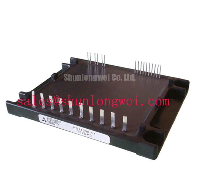
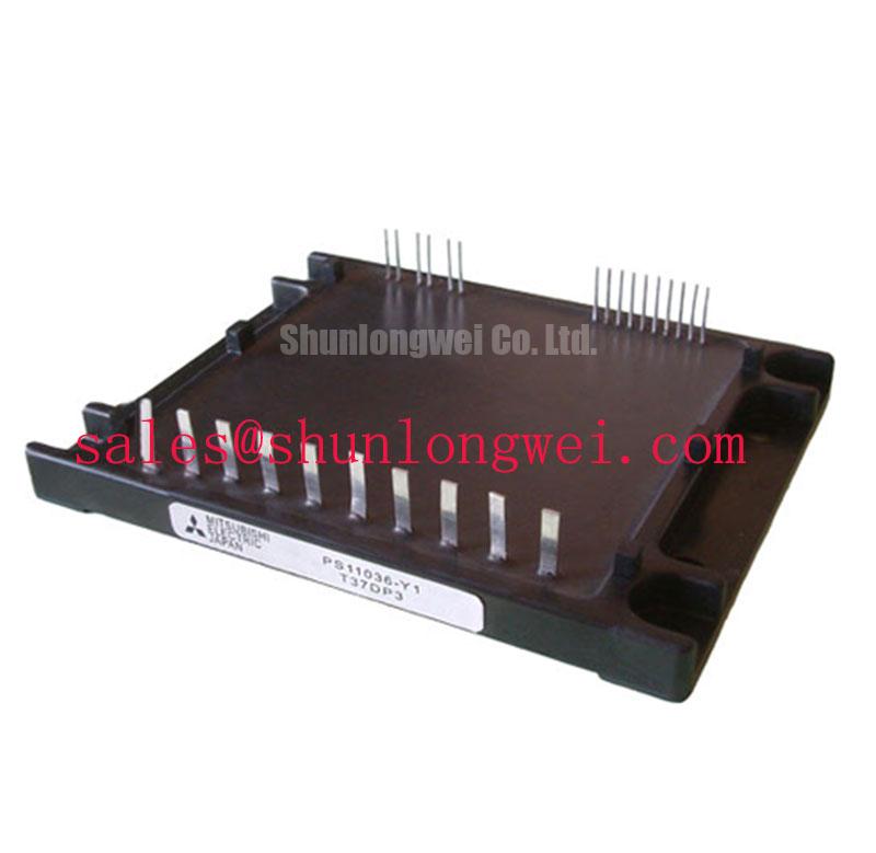
With the controller supply removed and the DC bus discharged, first compare each accessible power-terminal path of the installed PS11036-Y1 against the original circuit drawing and a known-good assembly before applying a diode-test probe. This prevents a polarity assumption from becoming a replacement error. The Mitsubishi Electric PS11036-Y1 DIPIPM is officially rated at VCES = 600 V, IC = 30 A at TC = 25°C, with VISO = 2500 VRMS for 1 minute. Its specified arm dead time is 2.2 µs, maximum collector-emitter saturation voltage is 2.9 V, and the recommended PWM operating range is 1 to 15 kHz.
| Official specification | Value or condition |
|---|---|
| Collector-emitter voltage, VCES | 600 V |
| Collector current, IC | 30 A continuous at TC = 25°C |
| Isolation voltage, VISO | 2500 VRMS, sinusoidal AC for 1 minute |
| Built-in arm dead time, tDEAD | 2.2 µs |
| Maximum saturation voltage, VCE(sat) | 2.9 V |
| Recommended PWM frequency | 1 to 15 kHz |
💡 Bench Tip: Use ESD-controlled handling and record cold-state diode-mode readings from the known-good assembly before judging any reading from a removed module.
A static electrical check cannot establish thermal health, but it can eliminate obvious terminal-path concerns before a controlled power test. For the PS11036-Y1, verify that the cooling interface is clean, that the module sits flat on its heat sink, and that no mounting stress is transferred into the package or terminals. The official 30 A continuous-current rating is stated at TC = 25°C; it is therefore a case-temperature condition, not a promise that the same current is available in every enclosed actuator drive.
Thermal capacitance is useful when evaluating brief overload events because the junction does not reach its final temperature immediately. A multi-RC thermal model represents heat spreading through several time-dependent paths between junction, case, interface material, and heat sink. This is an Engineering Calculation only when the applicable transient thermal-impedance data, pulse duration, initial case temperature, and actual loss waveform are available. Without the manufacturer’s transient impedance curve for this specific module, a numeric junction-temperature margin should not be inferred from the 2.9 V maximum VCE(sat) value alone.
As a Design Consideration, measure heat-sink temperature close to the module footprint during the real acceleration, holding, and regenerative deceleration sequence. Compare the temperature progression with the original drive under equivalent ambient and airflow conditions. A rise that differs materially from the reference can be related to contact quality, airflow, PWM loading, switching behavior, or a changed mechanical duty cycle. It should not be assigned to one cause without corroborating measurements.
For drives with regenerative braking, the DC-link braking chopper and braking resistor must be assessed as a system. Their role is to absorb returned motor energy when the DC link rises during deceleration. The 600 V VCES rating is the module’s specified blocking-voltage rating, while the actual braking threshold, resistor energy capacity, bus capacitance, and deceleration profile remain system-determined. Check the DC-link waveform at the module connection rather than only at a remote measurement point, because cable and layout inductance can alter the observed peak.
Apply thermal interface material as a thin, continuous layer according to the equipment’s documented assembly practice. Fasteners should be tightened evenly in the prescribed sequence so the baseplate contact remains uniform. Mounting torque is a Design Consideration unless specified by the original module documentation or equipment manufacturer. A heat sink that is visibly distorted, contaminated, or locally raised should be corrected before repeated powered testing.
Preventing Spurious Faults: High-Frequency Common-Mode Bearing Current Guidelines for PS11036-Y1
The built-in 2.2 µs arm dead time is an official shoot-through-protection feature of the PS11036-Y1. During repair verification, confirm that the controller command pattern, enable logic, and protection-state interpretation agree with this built-in timing. Do not assume that an external controller’s complementary PWM timing can be shortened or overridden merely because a replacement module powers up. Timing interaction must be verified on the actual gate-drive and phase-voltage waveforms.
Long motor cables can behave as transmission lines rather than simple conductors. A mismatch between cable impedance and motor-terminal impedance can reflect fast switching edges back toward the inverter and motor, producing voltage peaks that can approach twice the DC-link level in certain conditions. This is a Design Consideration, not an official PS11036-Y1 voltage specification. Engineers evaluating a precision stepper or BLDC servo motion actuator should capture phase voltage at the motor and at the inverter during the demanding portions of the motion profile.
When reflected-wave stress or bearing-current symptoms are suspected, inspect the motor cable shield termination, enclosure bonding, output filter condition, and common-mode choke installation against the original drive design. Output filtering must be selected by the system engineer because its inductance, capacitance, damping, cable length, control-loop behavior, and motor insulation all interact. The practical objective is to reduce unwanted common-mode current and terminal overshoot while validating peak voltage margins against the real DC-link voltage during switching tests.
A phase-current anomaly or intermittent fault may also arise from connector resistance, damaged cable insulation, grounding changes, or controller sensing behavior. Use an isolated differential measurement method and compare all three phase paths under identical command conditions. For background on system-level switching arrangements that can influence appliance motor-drive waveform evaluation, see Resonant Topologies in Home Appliances.
Control communication should remain separate from the power-module isolation assessment. In equipment where a motion controller exchanges commands or diagnostics over CAN bus, inspect the communication reference and shield strategy as part of the complete fault investigation. A communication disturbance does not, by itself, establish an IPM failure.
PS11036-Y1 Protection and Fault-Clearing Considerations
The supplied official specifications identify the voltage, current, isolation, dead-time, saturation-voltage, and PWM-frequency limits of the PS11036-Y1. They do not establish a Type I or Type II desaturation threshold, a short-circuit detection time, a short-circuit safe-operating duration, or a two-stage soft-turn-off profile for this part. These characteristics must therefore be verified from the original Mitsubishi Electric documentation and the host drive schematic before any protection tuning is attempted.
In a drive architecture that uses desaturation monitoring, the monitoring circuit examines the switching device’s on-state behavior for an abnormal rise that can accompany an overcurrent event. The response path commonly requires coordinated fault recognition, gate-control action, controller interlock, and DC-link energy management. A rapid hard turn-off in an inductive path can create a damaging overvoltage, while an overly slow response can increase device energy. The appropriate balance is an Engineering Recommendation based on measured loop inductance, load current, DC-link condition, and the equipment’s validated protection strategy.
For incoming diagnosis, compare the inactive-state and enabled-state behavior of the original and replacement boards before connecting a motor. Check control-supply sequencing, fault output logic, and the relationship between PWM commands and phase outputs with the DC bus limited by the approved test method. If the drive reports a fault immediately after enable, investigate command inhibition, controller supply stability, current-sense paths, and motor-terminal isolation before concluding that the power module is responsible.
The official maximum VCE(sat) = 2.9 V is a full-current switching-device parameter and should not be converted into a field desaturation trip value. A controller threshold is system-specific and must account for transient switching behavior, sensing blanking, temperature, driver topology, and the original protection circuit. Any change to a protection network should be validated with protected bench instrumentation and the equipment manufacturer’s service documentation.
When a cross-model evaluation is unavoidable, mechanical footprint, terminal assignment, control interface, voltage rating, current rating, isolation requirement, and protection behavior all require independent confirmation. The 7MBR15SA120 is a separate power-module listing that can be reviewed as part of a documented engineering comparison; it is not a drop-in replacement recommendation for the PS11036-Y1.
Benchtop Waveform Checks: Galvanic Gate-Drive Isolation and Switching Stress
The PS11036-Y1 official isolation rating is 2500 VRMS for 1 minute using sinusoidal AC. This rating must not be restated as reinforced isolation above 5 kV, nor does it establish a common-mode transient immunity value. Any requirement for reinforced insulation, a particular impulse withstand level, or a stated CMTI capability belongs to the complete drive insulation design and must be demonstrated using the relevant documentation and test method.
During bench waveform checks, use probes and instruments with suitable voltage and isolation ratings for the points being measured. Keep probe ground arrangements intentional, avoid accidental reference connections through measurement equipment, and inspect the gate-drive supply return path alongside the power return path. The aim is to distinguish a genuine command transition from a measurement artifact or an unwanted common-mode coupling event. Verify gate-drive behavior against a known-good channel and the host controller timing rather than relying on an assumed waveform shape.
Galvanic separation between control and power domains can limit the propagation of noise, but it does not remove the need for careful physical layout. As a Design Consideration, minimize high-current switching-loop area to suppress turn-off inductive overshoot, maintain practical clearance around energized conductors, and verify peak margins against the DC-link voltage during actual switching tests. The required spacing, insulation coordination, and enclosure conditions are determined by the final equipment design and its applicable standards.
Where the actuator includes a display or higher-level control board, the display interface is a separate integration subject. The MIPI Alliance DSI Display Interface Specification can guide interface-level verification where DSI is actually present, but it does not define PS11036-Y1 power-module behavior. Keeping display, communication, low-voltage logic, and power-switching measurements clearly separated helps isolate the source of intermittent system faults.