Content last revised on October 4, 2026
Assembly Integrity & Layout Architecture: Implementing Multi-Module Parallel Current Sharing for QM300DY-2H
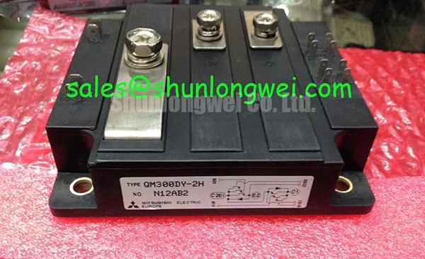
For incoming inspection, identify each terminal from the original module drawing and the host equipment schematic. Record cold resistance readings across corresponding terminals on each module using the same meter range and probe orientation. If a diode-mode reading is available across a documented junction or associated circuit path, compare it with a known-good unit under the same conditions rather than treating an assumed forward-voltage value as a pass criterion. A multimeter reading is a screening observation, not a substitute for a rated-voltage or load test.
In a parallel assembly, static current sharing depends on the devices’ actual on-state characteristics at operating temperature. The positive temperature coefficient described in some power-device designs should not be assumed for the QM300DY-2H without a model-specific characteristic curve. As a Design Consideration, the system engineer should compare measured current in each branch after thermal conditions stabilize, then check for differences in contact resistance, cooling, and connection length. Matching cold meter readings alone cannot establish sharing under load.
Dynamic balance needs its own check. Keep the gate-drive paths and high-current connections as symmetrical as the existing design permits, then compare branch current and switching waveforms during controlled commissioning. Documented terminal positions and mounting surfaces matter here: a mechanically interchangeable footprint does not prove equivalent electrical behavior. For a cross-model assessment, QM100HY-2H can be reviewed against the same schematic, ratings, drive requirements, and mounting drawing; its different model designation is not evidence that it is a direct replacement.
💡 Bench Tip: Keep the module and test leads under appropriate ESD controls, and record cold readings beside a known-good reference before applying powered tests.
QM300DY-2H Circuit Protection & Reliability: Calibrating High-Frequency Commutation Loop Inductance
Trace the commutation path on the equipment drawing before changing a snubber or busbar. Loop inductance adds a transient voltage during current change, so the observed switch voltage can exceed the DC-link voltage at turn-off. That relationship explains why a 2500 V rated module still needs waveform verification in its actual circuit. It does not yield a universal inductance limit or snubber value: switching current, path geometry, drive behavior, and permitted peak voltage are system-dependent.
As a Design Consideration, place any snubber connection close to the switching path it protects and keep outgoing and return busbar paths closely coupled where the equipment’s clearance and insulation design allows. A planar layout can reduce loop area, but clearance rules must come from the complete assembly design and its applicable safety requirements, not from the module voltage rating alone. Compare measured turn-off peaks with the DC-link condition and the verified device limits during switching tests. If an overshoot changes after a busbar or snubber replacement, inspect connection seating and the physical current path before assigning the fault to the module.
Check the role of adjacent power devices against the circuit rather than their position in the cabinet. For example, QM200HA-HK is a separate module to evaluate where an equipment design calls for it; its function and compatibility must be established from that design. Mitsubishi Electric’s power semiconductor resources provide broader device context, while model-specific limits remain the basis for a QM300DY-2H assessment.
Preventing Spurious Faults: PCB Gate Loop Layout Symmetry Guidelines for QM300DY-2H
At the gate-driver PCB, follow each drive and return conductor to the terminal identified in the original connection drawing. Do not infer a dedicated Kelvin emitter terminal from a generic gate-drive layout: its presence on this module has not been established by the supplied specifications. Where the documented connection scheme provides a separate drive return, route it independently of the high-current path as far as the equipment design permits. Otherwise, evaluate the available return path for voltage disturbance under switching current.
Symmetry is useful only when measured behavior supports it. With the appropriate isolated instruments and test procedure, compare commanded drive signals with the waveforms observed at the module connections. A fault indication coincident with commutation may warrant inspection of shared return impedance, connector seating, and routing beside the power bus. It does not identify a single failed part. Keep the driver, protection threshold, and switching network unchanged until the original schematic and observed waveforms show which part of the path needs attention.
For a commercial string inverter or micro-grid energy-storage converter, the QM300DY-2H should therefore be evaluated against the installed stage’s topology, drive circuit, cooling arrangement, and physical connections. The application name alone does not establish suitability. Discussions of other transistor technologies, including Mitsubishi Electric’s CSTBT technology, should not be used to assign IGBT-specific gate or switching characteristics to this Darlington module.
QM300DY-2H Operational Boundaries: Evaluating Optocoupler vs Digital Coreless Transformer Limits
Identify the isolation barrier in the driver assembly, not in the QM300DY-2H rating line. The supplied 2500 V figure is a rated module voltage (Official Specification); it is not a stated reinforced-isolation rating for an optocoupler, digital isolator, or complete converter. Before comparing driver technologies, obtain the installed driver’s documentation and verify its insulation rating, operating conditions, output behavior, and applicable system requirements. Treat insulation reliability and safety compliance as assembly-level questions unless the relevant component documentation states a specific tested claim.
Common-mode transient immunity also belongs to the selected isolation device and its implementation. As a Design Consideration, examine whether a measured switching transient coincides with an unintended gate pulse, then compare the driver input, isolated output, and module-side signal using a suitable measurement setup. The driver choice should be settled against those waveforms and the equipment’s required margins, rather than an assumed immunity threshold for QM300DY-2H.
If a repeat fault follows a driver-board change, first confirm terminal mapping, return-path continuity, and the timing of the protection response against the original circuit documentation. The discussion of three-phase switching and transient behavior in The 1200 V CoolSiC™ MOSFET Advantage in Three-Phase Power Conversion can inform that system-level investigation, but its SiC MOSFET characteristics are not specifications for this Darlington module.