
Content last revised on October 4, 2026
RM500HA-H Dead-Short Protection and Fuse Coordination
Isolate the rectifier assembly, identify the marked power terminals, and check the cold-state diode polarity before fitting an RM500HA-H. Record the meter reading in both directions and compare it with a known-good unit tested under the same conditions; a diode-range reading alone cannot establish the module’s high-voltage condition.
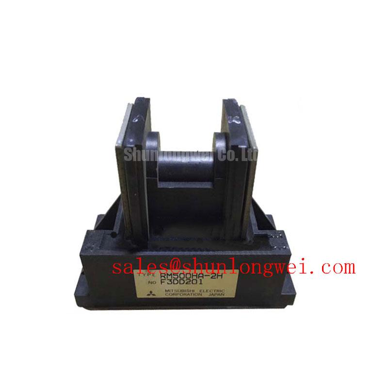
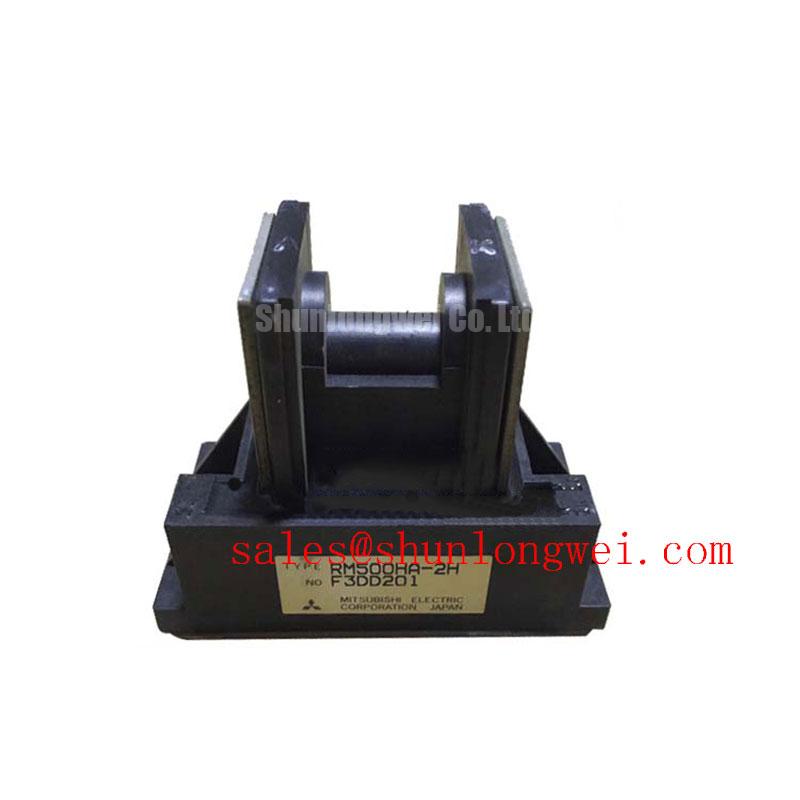
The RM500HA-H is a Mitsubishi Electric diode module with a stated 1600 V voltage rating and 500 A current rating. These are Official Specifications supplied for this product, not values to use as a substitute for its complete datasheet. Before installation, the equipment engineer still needs the original terminal drawing, rating conditions, thermal data, and mounting instructions. Mitsubishi Electric’s diode modules lineup provides manufacturer context for this device category.
On a bench inspection, begin with the circuit drawing rather than the fuse label. Trace the prospective fault path through the transformer or supply, rectifier, DC link, and RM500HA-H terminals. A short circuit elsewhere in that path can expose the diode to a current pulse whose duration and peak depend on the complete installation. Its 500 A rating does not, by itself, state how much short-circuit energy the module can withstand.
For a proposed semiconductor fuse, obtain the fuse maker’s clearing data at the applicable voltage and prospective fault current. Then compare its total clearing I²t with the diode’s documented surge-current and I²t limits under the relevant conditions. This is a Design Consideration requiring both manufacturers’ data and the equipment’s fault-current assessment. No RM500HA-H surge-current or I²t value is provided here, so a protective coordination result cannot be asserted. In particular, “Type 2 coordination” and an absence of physical damage cannot be guaranteed from the voltage and current ratings alone.
Terminal work deserves the same discipline as fuse selection. Match the module’s marked polarity and terminal layout to the original assembly drawing before moving busbars. Inspect contact faces, fasteners, and insulating clearances without assuming that another diode module shares the same mechanical interface. The tightening torque must come from the applicable module documentation and hardware specification; an unverified torque figure is not an RM500HA-H factory requirement.
💡 Bench Tip: Discharge and verify the DC link before using the diode range or disturbing a module terminal. With the module disconnected from parallel circuit paths, measure in both directions using the same instrument and lead placement used for the reference unit. An unexpected reading calls for checks of probe contact, circuit isolation, and the original terminal diagram before the module is judged defective.
For a cross-model maintenance assessment, RM500CZ-M is a separate device to compare against the required circuit position. Its electrical limits, polarity, terminal arrangement, dimensions, and mounting instructions must be checked independently; similarity in a model name does not establish interchangeability.
AC Line Surges and the RM500HA-H Rectifier Position
When a rectifier is exposed to an incoming-line transient, the voltage measured at its terminals matters more than a nominal line-voltage description. Trace where line protection, transformer impedance, rectifier connections, and DC-link components sit relative to the RM500HA-H. Its stated 1600 V rating is an Official Specification, but it does not establish the peak transient that will appear across the diode in a particular cabinet.
As a Design Consideration, an engineer evaluating surge protection should measure or model the relevant line and switching transients, then check the resulting diode-terminal voltage against the limits and test conditions in the complete factory datasheet. A metal oxide varistor or an RC snubber can be assessed as part of the equipment-level protection circuit. The choice of device, placement, energy capability, and thermal duty depends on the supply and fault environment; none can be prescribed from the module’s two stated ratings.
Surge immunity testing is an equipment-level matter. IEC 61000-4-5 addresses surge test methods, but the presence of this diode does not establish that an assembled power supply passes a surge or EMC test. If a transient record is available, compare the measurement point, probe setup, and operating state before attributing a peak to the module. A pulse observed on a long measurement lead can differ from the voltage at the diode terminals.
In a medium-frequency induction melting or hardening furnace power supply, the module could be evaluated for a rectifier position only after the actual topology and duty cycle are known. That application is a compatibility assessment, not a stated factory designation for RM500HA-H. If the system drawing calls for a separate complementary rectifier-stage device, RM100HA-20F can be reviewed against that specific position’s ratings and connections; its suitability cannot be inferred from this module’s specifications.
Reverse Recovery Measurements Without Assuming Missing Limits
A cold diode-range test establishes useful polarity and gross continuity information, but it says little about reverse recovery during commutation. When current transfers away from a conducting diode, a temporary reverse current can occur before blocking is established. Its waveform depends on the preceding forward current, current-change rate, temperature, and surrounding circuit. Mitsubishi Electric’s power semiconductor information is a useful manufacturer starting point for the wider device and application context.
The supplied RM500HA-H specifications do not include peak reverse recovery current, reverse recovery time, or a defined recovery-test condition. It would therefore be unsound to label a captured peak as within the module’s factory limit, or to call its recovery “soft,” without the applicable datasheet and measurement conditions. For an installed unit, an engineer can record diode current and terminal voltage during the relevant commutation event, taking care that the probes and acquisition setup can resolve the waveform without altering the circuit.
Compare those captures at repeatable operating points and against an established reference path. A change in the measured reverse-current shape may warrant examination of busbar layout, snubber components, temperature, and the commutating device as well as the diode. It is not a single-cause diagnosis. Minimize unnecessary connection-loop inductance to limit switching overshoot, then verify the resulting peak voltage and thermal behavior in the actual assembly; the acceptable layout is system-determined.
Reverse recovery can also affect conducted and radiated noise from the assembled converter. That observation is a Design Consideration, not an EMC compliance statement about the diode module. For broader comparisons involving device ratings, protection, and circuit fit, the Power Semiconductor Selection Guide provides a framework to use alongside the original equipment documentation.
Thermal and Terminal Checks: Why Gate-Trigger Tuning Does Not Apply
The RM500HA-H is identified here as a diode module, not a gate-triggered thyristor. Gate firing pulse rise time, back-porch holding current, and multi-pulse firing are therefore not tuning instructions for this product. If those terms appear in the furnace control documentation, locate the thyristor or other controlled device to which they refer before changing a firing board. Applying gate-drive troubleshooting to a diode position can divert attention from the rectifier’s actual current path.
For this module, follow the heat path instead. Confirm the mounting surface, contact condition, fastener arrangement, and cooling interface against the original equipment and module instructions. Record temperatures at reproducible load conditions and check for changes alongside terminal-voltage and current measurements. The supplied specifications do not state a thermal-resistance value, permitted case temperature, or mounting torque, so none should be treated as a factory limit on this page.
A rising terminal temperature may justify inspection of the electrical joint, while a rising module temperature may call for assessment of load current and cooling. Neither observation proves a cause by itself. For replacement work, verify the 1600 V and 500 A ratings against the original design requirements, then resolve the remaining datasheet-dependent checks—terminal polarity, surge capability, thermal limits, insulation requirements, and mechanical fit—before energizing the assembly.