

Content last revised on September 22, 2026
SGG600SD120TK Specifications and Service Inspection
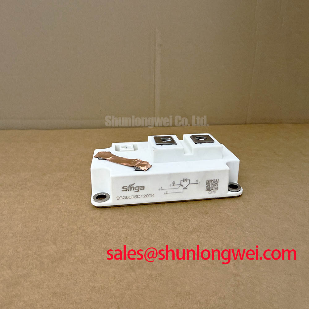
Begin service inspection by isolating the furnace power circuit, checking the module marking against the equipment documentation, and verifying the stated voltage and current limits before any electrical test. The Toshiba SGG600SD120TK is a dual IGBT module intended for evaluation in high-current power-conversion equipment, including medium-frequency induction melting and metal-hardening power supplies.
| Parameter | Official Specification |
|---|---|
| Collector-emitter voltage, VCES | 1200 V |
| Continuous collector current, IC | 600 A at TC = 80°C |
| Gate-emitter voltage, VGES | ±20 V |
| Collector-emitter saturation voltage, VCE(sat) | 2.10 V typical |
| Short-circuit withstand time, tSC | 10 µs minimum |
| Isolation voltage, VISOL | 2500 V AC for 1 minute |
| Package configuration | Dual, 2-pack |
Transient Dynamics & Electrical Design: Thermal Interface Material Spreading across SGG600SD120TK
Thermal installation should start with a clean inspection of the copper baseplate, heatsink surface, mounting hardware, and thermal interface material. The objective is uniform contact across the module footprint so that the stated 600 A continuous collector current at TC = 80°C is evaluated under the actual cooling conditions of the furnace cabinet. The published electrical ratings do not replace a thermal verification of the assembled system.
Apply thermal compound as a thin, continuous layer suitable for the selected heatsink surface, then tighten the mounting hardware using the module manufacturer’s mechanical instructions. A torque value is not included in the supplied parameter set, so the equipment service manual or Toshiba mechanical specification should control the final procedure. Excessive tightening can distort the package or produce uneven contact, while insufficient pressure can leave localized thermal resistance at the baseplate.
After installation, inspect for visible compound displacement, baseplate rocking, uneven fastener seating, and contamination around the power terminals. The thermal path should be checked during a controlled operating test by comparing temperatures at equivalent mounting points and monitoring the temperature rise at the electrical connections. A rising terminal temperature may require inspection of conductor preparation, contact pressure, busbar alignment, and current distribution rather than immediate replacement of the module.
The dual configuration is relevant when reviewing the original circuit topology and current path. The replacement assessment should confirm terminal identity, polarity, connection geometry, creepage requirements, and the cooling arrangement used by the equipment manufacturer. The module’s 2500 V AC isolation voltage for 1 minute is an official specification for the stated test condition; it should not be treated as a complete certification of the assembled furnace.
Maintenance Note: Schedule periodic heatsink cleaning, inspect thermal interface material for drying or displacement, and compare contact temperature across the power terminals during preventive maintenance.
Transient Dynamics & Electrical Design: Pulse Transformer Isolated Firing Circuit on SGG600SD120TK
A pulse transformer firing circuit should be checked as a complete gate drive path, including the controller output, transformer insulation, secondary wiring, gate network, return path, and electrical timing at the module terminals. The supplied specifications identify a ±20 V gate-emitter voltage rating, but they do not provide IGT, VGT, gate pulse current, gate rise-time, holding-current, or recommended pulse-train values. Those values must therefore be taken from the applicable Toshiba documentation and verified against the actual circuit.
For a medium-frequency induction power supply, designers should examine whether the firing pulse remains correctly shaped under operating temperature, switching frequency, supply variation, and transformer loading. A pulse that appears correct at the controller may show ringing, insufficient amplitude, or timing displacement at the module terminals. Oscilloscope measurements should use an appropriate isolated differential method and should compare the gate-emitter waveform with the known-good firing channel.
The requested gate current rise target above 1 A/µs should not be treated as an official SGG600SD120TK rating because it is not included in the supplied factory data. It may be evaluated as a system design requirement only when supported by the original gate-drive design and the manufacturer’s switching guidance. Pulse repetition, back-porch holding current, and multi-pulse firing should be selected after confirming the device’s published gate characteristics and checking that the transformer does not saturate during the intended duty cycle.
When several power devices operate in parallel or in coordinated bridge positions, the control system should provide clear dead-time behavior and prevent simultaneous unintended commands. The exact timing is system determined. Validation should include startup, shutdown, abnormal firing, loss of feedback, and recovery from a protection trip. The Evolution of Negative Off-Bias Gate Drive Circuits provides useful background for evaluating off-state gate control, but it does not establish a mandatory voltage for this module.
For a neutral comparison during procurement, engineers may also review the electrically related SG800EX21. Any suitability decision should be based on the original circuit ratings, mechanical fit, gate requirements, thermal path, and verified switching behavior rather than on current rating alone.
SGG600SD120TK Thermal-Electrical Optimization: Fuse Total Clearing I2t versus Device Melt Practical Tuning
Short-circuit protection must be coordinated with the complete furnace power circuit. The SGG600SD120TK has an official 10 µs minimum short-circuit withstand time, but the supplied information does not include the module’s allowable I2t value, semiconductor fuse coordination table, or a specific fuse part number. A fuse cannot be selected responsibly from the 600 A rating alone.
The protection study should compare the fuse manufacturer’s pre-arcing and total clearing I2t data with the device limits published for the exact module revision. The analysis should also include prospective fault current, DC link or AC source impedance, busbar inductance, fault detection delay, fuse voltage rating, and the actual current path through the dual module. The clearing result should be verified by testing or by a documented coordination study that reflects the installed circuit.
During service, inspect fuse holders, bus connections, pressure contacts, and signs of repeated thermal cycling. A fuse that has operated may reflect a gate-control fault, commutation problem, insulation event, cooling issue, or external short circuit. The diagnostic process should record the operating state, protection signal timing, gate waveforms, and condition of surrounding conductors before the module is condemned.
For the upstream or complementary rectifier stage, engineers may evaluate the TT570N16 as a separate component in the power-conversion chain. It should not be assumed to be a direct substitute or a guaranteed companion device. Voltage, current, commutation, thermal, and mechanical requirements must be checked for the specific furnace topology.
Any claimed zero-damage result from a dead-short event would require verified system test evidence and the relevant manufacturer coordination data. The available official parameters support a protection review, but they do not support a guaranteed field outcome or a universal fuse recommendation.
SGG600SD120TK Thermal-Electrical Optimization: Coordination of Primary Spark Gaps, MOVs, Practical Tuning
Surge protection should be reviewed from the incoming supply through the transformer, rectifier, DC link, switching bridge, and gate-control circuits. The SGG600SD120TK’s 1200 V collector-emitter voltage rating and 2500 V AC isolation rating for 1 minute establish important device limits, but they do not define the correct MOV voltage, spark-gap setting, RC snubber value, or impulse-current rating for an installed induction furnace.
A protection study should identify the maximum normal line voltage, transient source, available fault current, wiring arrangement, grounding system, and required coordination between the primary protection and the semiconductor switching stage. MOV selection should account for continuous operating voltage and energy duty, while spark gaps and upstream arresters should be evaluated for let-through voltage, response, and coordination with the equipment enclosure.
RC snubber stages may be considered where measured switching transients or commutation behavior justify them. Their values should be established from the actual circuit waveform, component voltage stress, pulse energy, and thermal behavior. Engineers should verify peak voltage at the module terminals during controlled switching tests rather than infer protection adequacy from the nominal DC-link voltage.
The ROHM short-circuit withstand time guidelines offer broader semiconductor protection context. They should be used as an industry reference alongside the Toshiba documentation, not as a substitute for the SGG600SD120TK’s own gate, surge, and short-circuit data.
Before energizing a repaired furnace, verify terminal tightness, insulation condition, cooling airflow, gate isolation, protection interlocks, and the recorded transient waveforms. The system integrator should confirm every unlisted parameter from the original equipment documentation and the applicable Toshiba technical material.