


Content last revised on November 5, 2026
Assembly Integrity & Layout Architecture: Implementing Driver Power Stage Start-Up Inrush Mitigation for SK35GAL12T4
Trace the auxiliary supply, driver enable, and DC-link precharge sequence to establish when the SK35GAL12T4 gate first enters a controlled off state. As a Design Consideration, the control system should inhibit switching until the driver supply is stable and its undervoltage lockout has released correctly. Where the equipment uses negative gate bias, check that the negative rail is established before the power stage is enabled and remains controlled during shutdown.
Negative turn-off bias is a system design choice whose magnitude must respect the device gate limits and driver capability. It should not be assigned from a generic IGBT practice. During startup testing, observe the voltage directly between the relevant gate and emitter connections, using a measurement arrangement suitable for the circuit’s common-mode voltage. A clean waveform at the controller output does not establish what reaches the module through the isolated driver and connecting conductors.
Separate DC-link charging current from gate-driver startup behavior. The precharge circuit controls charging of the link capacitance, while the driver interlock controls the switching state. Inspect the precharge bypass command and the switching enable command as separate events. If the link rises unexpectedly or the driver repeatedly resets, correlate the auxiliary supply waveform with those commands before attributing the behavior to the module.
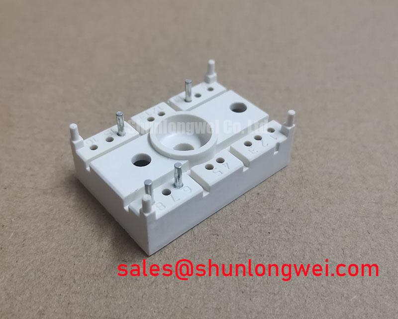
For the gate layout, the engineering objective is a short outgoing path with a closely associated return path. Shared impedance between the power-current return and the gate reference can introduce emitter-reference movement during switching. Designers should examine the actual terminal diagram and board routing rather than assume that a separate driver-reference terminal is present. Keep sensitive control conductors away from high-current commutation paths, with insulation spacing determined by the equipment’s electrical requirements.
Miller-induced gate movement deserves attention when a nearby switching node changes voltage rapidly. As a Design Consideration, evaluate the driver’s turn-off impedance, gate-loop coupling, and any supported active clamping function against the measured gate waveform. An observed excursion can also contain probe-loop pickup or reference movement, so check measurement integrity before changing the drive network. Select damping and bias through controlled switching evaluation within the component limits.
Pro Tip: Keep the commutation paths compact and balanced where the topology permits, then use a controlled double-pulse test to check turn-off overshoot and unintended gate movement.
Manufacturer resources at the Semikron-Danfoss Power Electronics & Modules Official Hub provide the appropriate context for module documentation and application guidance. When assessing a different mechanical platform, the Semikron MiniSKiiP® Power Modules range illustrates a separate product family; its assembly methods should not be transferred to this Semitrans package without a corresponding mechanical specification.
Transient Dynamics & Electrical Design: Suppression of Reflected-Wave Overvoltage at the SK35GAL12T4
Measure switching transients at the module terminals and the motor terminals separately when investigating a long motor cable. As a Design Consideration, a cable behaves as a transmission line when its propagation time becomes significant relative to the applied voltage transition. An impedance discontinuity at the motor can reflect the incident wave, producing a motor-terminal excursion approaching twice the incident step under idealized conditions.
That reflected-wave mechanism does not establish that the SK35GAL12T4 collector-emitter voltage doubles. Local commutation inductance and motor-cable reflections involve different measurement locations and current paths. Compare the module switching waveform with the motor-terminal waveform using suitable differential probes, and record operating state, cable configuration, and probe connections. This separates a local turn-off overshoot problem from a cable-end insulation stress problem.
An output reactor or dv/dt filter should be evaluated against cable characteristics, motor insulation requirements, switching behavior, and load current. As an Engineering Recommendation, select the filter through the drive and filter manufacturers’ application criteria, then verify its effect under the intended operating conditions. Include filter heating, voltage drop, and control interaction in that assessment. A filter that reduces a motor-terminal peak does not automatically resolve an excessive local collector-emitter peak.
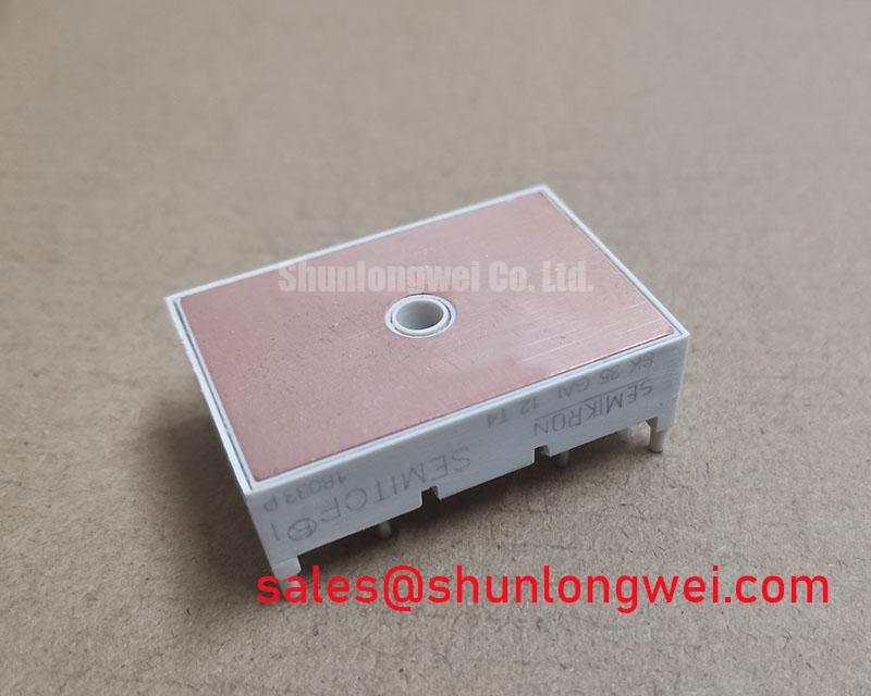
The mechanical installation affects the thermal conditions under which those switching measurements remain meaningful. Inspect the heatsink contact surface, mounting hardware, and interface material before rebuilding the assembly. Apply the thermal interface material according to the approved package assembly procedure, accounting for surface flatness and the material’s application method. Assigning a generic layer thickness can produce inconsistent contact when transferred between different surfaces and materials.
Where the mounting drawing specifies multiple fasteners, follow its tightening sequence and torque requirements so that contact pressure develops as intended. Cross-pattern tightening is a general assembly consideration only where compatible with the prescribed mounting method. Spring washers, pressure plates, and cooling from additional surfaces require explicit mechanical support in the assembly design; they should not be added as assumed features of the SK35GAL12T4.
A cross-model review should distinguish the required electrical function from a shared manufacturer name. The SKM400GB066D can be included in a Semikron sourcing comparison, but its suitability must be established from its own voltage class, circuit configuration, terminal geometry, and thermal requirements. The comparison below keeps confirmed SK35GAL12T4 values separate from attributes that require a datasheet-level comparison.
| Comparison item | SK35GAL12T4 | SKM400GB066D |
|---|---|---|
| Manufacturer | Semikron | Semikron |
| Voltage rating | 1200 V — Official Specification | Consult Datasheet |
| Current rating | 50 A — Official Specification | Consult Datasheet |
| Package designation | Semitrans — Official Specification | Consult Datasheet |
| Replacement qualification | Match circuit position, terminals, driver, and cooling interface | Compare these interfaces before considering substitution |
For electric material handling equipment, including low-voltage forklift traction systems, engineers should first establish whether the existing converter topology and driver interface make this voltage class and package relevant. This is a compatibility assessment rather than an application designation. In regenerative operation, trace the actual energy path: battery acceptance, DC-link control, and any braking chopper each affect the electrical conditions presented to the switching stage.
If the equipment includes a braking resistor, evaluate its pulse-energy capability and cooling against the machine’s braking duty. Those system requirements cannot be derived from the module’s current rating. For broader interpretation of switching limits and test waveforms, The Ultimate IGBT Knowledge Base provides supporting technical context alongside the equipment-specific acceptance procedure.
SK35GAL12T4 Operational Boundaries: Evaluating Megohmmeter and DC High-Potential Terminal-to-Baseplate Limits
Disconnect the module from sensitive driver and control electronics before planning a terminal-to-baseplate insulation measurement. Establish which terminals the approved test procedure joins together, where the test voltage is applied, and how stored charge is removed afterward. An insulation resistance measurement and a dielectric withstand test have different purposes; their voltages, durations, and acceptance criteria are not interchangeable.
The supplied electrical ratings do not establish a terminal-to-baseplate insulation test voltage or resistance threshold. Use the manufacturer’s applicable insulation specification and the equipment service procedure to define those acceptance conditions. Applying a convenient megohmmeter setting without that basis can stress connected circuitry or create a result that has no valid pass criterion.
As a Design Consideration, inspect the exposed insulation surfaces around the power terminals for conductive contamination, moisture, tracking, and mechanical damage. Surface leakage can influence a resistance measurement without identifying the condition of an internal insulating structure. Record the test configuration and environmental condition so that an unexpected result can be assessed against a comparable measurement rather than treated as a single-cause diagnosis.
Creepage follows the insulating surface between conductive parts, while clearance follows the shortest path through air. In the installed assembly, inspect both around terminal hardware, busbars, mounting brackets, and nearby chassis metal. Determine the required spacing from the applicable equipment standard and insulation coordination conditions. The 1200 V semiconductor blocking rating does not by itself define the assembly’s creepage or clearance requirement.
Where contamination is present, use a cleaning method compatible with the module housing and surrounding materials, then allow the assembly to reach the condition required by the test procedure. Recheck displaced insulating barriers and cable supports during reassembly. Keep insulation-test records separate from switching-test records, and return the power stage to service only after the relevant electrical checks and protective interlocks meet the equipment’s acceptance criteria.