
Content last revised on October 14, 2026
SKD110-18 Replacement and Application Checks
- Isolate the supply, verify stored energy has discharged, and record cold terminal measurements with the module disconnected from parallel circuit paths.
- Match the SKD110-18 terminal markings to the equipment schematic before reconnecting AC inputs and DC outputs.
- Inspect the mounting surface, thermal interface, and cooling passages for contamination, uneven contact, or displaced material.
- Compare the replacement specification with the equipment service record, including voltage designation, current rating conditions, and protective fuse coordination.
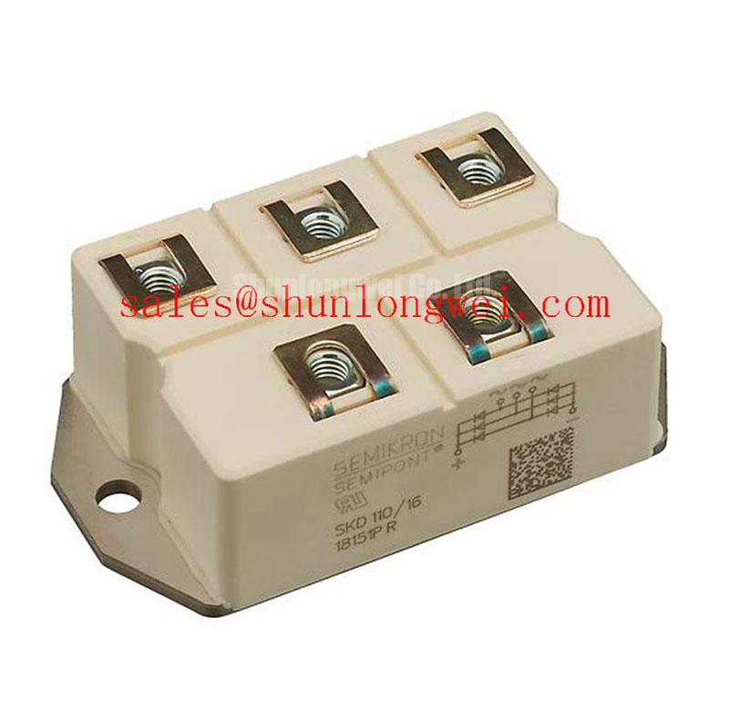
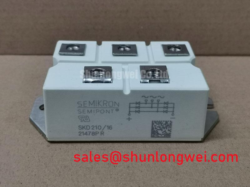
The SKD110-18 is identified as a Semikron bridge rectifier module in a SEMIPONT package. Its rectification function must be distinguished from the firing control of a thyristor stage: a diode bridge has no adjustable firing angle or gate-drive connection. This distinction matters when tracing a cabinet schematic or assessing a replacement.
| Product reference | Value | Specification status |
|---|---|---|
| Model | SKD110-18 | Product identifier |
| Manufacturer | Semikron | Brand identification |
| Package | SEMIPONT | Supplied package designation |
| Voltage reference | Not established here | Consult the matching datasheet |
| Current reference | Not established here | Consult the matching datasheet |
Obtain the matching manufacturer rating definitions, thermal conditions, terminal drawing, and assembly instructions through the Semikron-Danfoss official power electronics hub.
Benchtop Waveform Tuning: Mitigating Stress via Phase-Controlled Rectification, Firing Angle on SKD110-18
Trace the controlled switching stage separately from the SKD110-18 before adjusting firing commands. Design Consideration: changing a thyristor controller’s firing angle changes the controlled converter’s behavior, not the diode bridge’s intrinsic conduction command. Record the actual circuit topology before interpreting DC voltage, input current, or reactive power measurements.
A firing-angle sweep belongs to the controlled stage’s commissioning procedure. Its AC-to-DC transfer characteristic depends on whether the circuit is fully controlled or partly controlled, whether current remains continuous, and how the load stores energy. Measure input voltage, input current, and DC output together; use a suitable power analyzer to separate displacement effects from waveform distortion rather than inferring power factor from the firing command alone.
For repair-material comparison, SKD110/16 is a related model to assess, not an automatic substitute. Compare blocking-voltage designation, current rating conditions, terminal arrangement, mounting geometry, and surge capability before accepting an interchange.
When evaluating auxiliary rectification in a grid-tied static var compensator or thyristor-switched capacitor cabinet, distinguish that auxiliary function from the main reactive-power switching branch. The SKDH100/14 also warrants a separate topology review; its connections and control requirements must not be inferred from the SKD designation.
Transient Dynamics & Electrical Design: Surge Energy Dissipation and Clamping Voltage on SKD110-18
Compare the residual voltage at the bridge terminals with the device’s documented blocking limits when evaluating an input protection network. Design Consideration: an MOV’s nominal voltage alone does not establish protection; its clamping behavior, incoming surge conditions, connection inductance, and coordination with upstream protection determine the stress reaching the rectifier.
The relevant surge-immunity reference is IEC 61000-4-5, not “IEEE 61000-4-5.” It addresses equipment testing and does not establish that this module independently satisfies an installation’s immunity requirements. The system test plan should define the applicable ports, coupling arrangement, and acceptance criteria.
RC damping should address measured ringing in the actual circuit. Select its electrical and thermal characteristics from the observed transient and operating waveform, then verify resistor heating and capacitor stress. Keep protective connections compact where practical, with placement finalized through system measurements rather than an arbitrary component recipe.
| Fuse coordination check | Required comparison |
|---|---|
| Fault clearing | Fuse total clearing I²t against the module’s applicable withstand specification |
| Surge conditions | Manufacturer pulse duration, initial temperature, and surge-current conditions |
| Installation conditions | Prospective fault current, circuit voltage, and fuse interruption capability |
A downstream bootstrap supply belongs to its associated switching circuitry, not to the bridge itself. If present, assess recharge opportunity, capacitor ripple, and charging-diode recovery against that circuit’s operating sequence.
SKD110-18 Thermal-Electrical Optimization: Junction-to-Heatsink Heat Dissipation in H Practical Tuning
Check heatsink flatness and the thermal-interface contact pattern before refitting the module. Design Consideration: junction-to-case thermal resistance describes one part of the heat path; interface resistance, heatsink performance, and airflow also influence operating temperature. Do not infer baseplate material from the package name.
Apply the specified interface material using the manufacturer’s assembly method. Uneven coverage, debris, and mechanical distortion can compromise contact. Mounting-fastener torque and power-terminal torque are separate requirements; use their respective instructions and a calibrated tool rather than transferring a generic screw value.
Maintenance Note: Trend terminal and heatsink temperatures under comparable load conditions, and inspect the cooling path when either trend changes.
Set cleaning and interface-inspection intervals from contamination levels, thermal trends, and equipment maintenance instructions. Check for moisture before re-energization after temperature transitions. The IGBT Design & Integration resource offers broader system context, while the manufacturer’s MiniSKiiP power module information concerns a different product family and should not supply SKD110-18 mounting instructions.