Content last revised on September 19, 2026
SKD145/18 Operational Boundaries: Evaluating Thermal Duty Cycle Management of Bypass Contact Limits
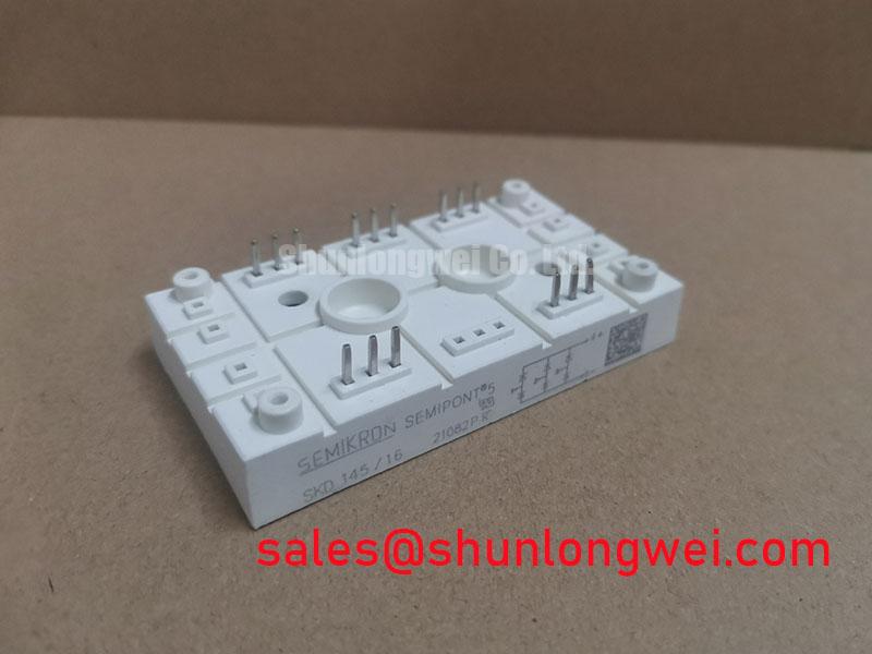
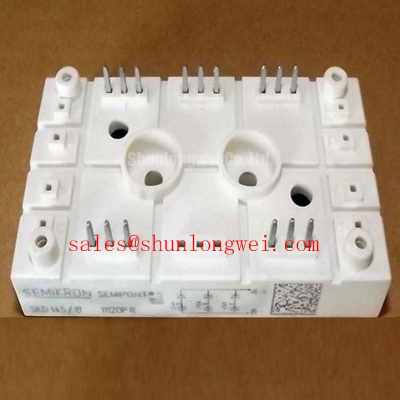
In a high voltage three phase motor solid state soft starter, first establish where the SKD145/18 bridge rectifier sits in the original power architecture before treating it as a direct replacement. A soft starter commonly controls motor acceleration through phase angle control in a separate controlled power path, while rectification may support a dedicated DC supply or another defined subsystem. The system integrator should verify the original schematic, conductor routing, terminal designations, and bypass contactor sequence. The 1800 V voltage rating and 145 A current class identify the electrical boundary of this particular module; they do not independently define the permissible motor size, starter duty, or bypass strategy.
Locked rotor current can be several times the motor rated current during starting. Phase angle control is often evaluated to reduce the initial electrical and mechanical shock, but the resulting thermal duty must be assessed at the assembly level. Design Consideration: record the starting profile, repetitive start frequency, cooling state between starts, cabinet ambient conditions, and the timing at which the bypass contactor transfers the motor to line operation. This information allows an engineer to distinguish a transient overload event from a sustained overload or a bypass sequencing problem.
Fuse coordination should be reviewed against the protection device documentation and the rectifier module datasheet rather than selected from current rating alone. Confirm that the fuse I2t information, prospective fault energy, conductor capability, and contactor interruption assumptions align with the equipment design. A fuse can protect a faulted circuit under defined conditions, but it does not correct poor thermal contact, incorrect terminal phasing, or an unsuitable repetitive duty cycle.
With the supply isolated and discharged, check that each external terminal connection is mechanically secure and electrically consistent with the documented bridge topology. Compare readings with the original circuit diagram and a known sound assembly where available. An unexpected reading may result from parallel circuitry, suppression components, measurement lead polarity, or a module fault; isolate relevant connections before drawing a result from a bench meter test.
Field Alert: Do not tighten mounting or power connections by feel alone, because uneven mechanical loading can distort a module interface or create a high resistance joint.
Assembly Integrity & Layout Architecture: Implementing Baseplate Thermal Resistance for SKD145/18
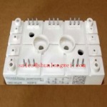
The Semipont package should be mounted to a clean, flat heatsink interface so heat can move consistently from the module baseplate into the cooling structure. The relevant thermal path is not a single component characteristic in field service: it includes the module contact surface, thermal interface material, heatsink flatness, clamping distribution, airflow or liquid cooling performance, and the actual conduction waveform. Official electrical ratings cannot be used as a substitute for a completed thermal verification.
Design Consideration: apply thermal interface material as a controlled, continuous film according to the material supplier guidance and the equipment manufacturer’s assembly method. The objective is to fill microscopic surface irregularities without creating a thick insulating layer or leaving dry contact regions. During removal, uneven paste transfer, localized discoloration, or differing fastener witness marks can be useful evidence that the previous pressure distribution requires investigation.
Use the original equipment documentation or the applicable Semikron mechanical drawing to determine the correct mounting hardware and torque. General industry mounting values must not be represented as an SKD145/18 factory requirement. The system engineer should use a calibrated process, tighten in an even sequence, and confirm that busbars land naturally on the terminals without applying side load to the package. A busbar that has to be forced into position can transfer stress into the module as temperature changes.
Layout also affects serviceability. Keep the high current path compact and geometrically balanced where the existing design permits, especially where conductors run beside each other in opposite directions. This is an Engineering Recommendation intended to reduce parasitic inductance and uneven current sharing under transient conditions. For background on thermal interface choices and cooling architecture, see The Advanced Thermal Management Revolution.
After reassembly, validate thermal behavior under a controlled load profile that represents the actual equipment duty. Measure heatsink response and inspect for unequal heating patterns with suitable instruments. A local temperature difference can point to several conditions, including cooling path restriction, connection resistance, unbalanced loading, or measurement placement. It should trigger further verification rather than a single cause assumption.
Benchtop Waveform Tuning: Mitigating Stress via Evaluating Post Surge Reverse Voltage Blocking on SKD145/18
Where the service event includes a mains disturbance, stalled motor event, or abnormal current pulse, evaluate the rectifier in the context of its reverse voltage recovery and the surrounding network. The installed circuit must keep the SKD145/18 within its 1800 V specified voltage rating during all verified operating and transient states. A nominal supply reading alone does not establish this condition, because source impedance, transformer leakage, cable inductance, switching sequence, and connected loads can influence the observed waveform.
The sinusoidal half cycle surge rating, commonly shown in rectifier datasheets as ITSM, is a specific test parameter with stated conditions. It is not interchangeable with continuous current capability or repetitive starting duty. Where the original Semikron datasheet provides an ITSM value and associated conditions, compare it directly with the protection analysis and the measured event assumptions. Do not infer a surge rating from the 145 A current class.
A controlled bench review should begin with safe isolation, discharge verification, and confirmation that the intended test setup reproduces the relevant load and source conditions. Use appropriately rated measurement equipment to observe line side and DC side behavior, then compare the captured voltage and current waveforms to the original circuit expectation. Ringing or an unexpected reverse voltage pattern may indicate an interaction between wiring inductance, snubber components, transformer behavior, or switching timing. Verification against a known good signal path is more defensible than diagnosing the module from waveform appearance alone.
Semikron Danfoss maintains an official power electronics and modules resource that can help engineers locate manufacturer context when checking product family documentation. For a physically different current class within the same naming family, SKD82/18 can be reviewed as a separate engineering comparison point. It must not be assumed equivalent: voltage rating, current duty, mechanical fit, thermal path, terminal arrangement, and the equipment protection study all require independent verification.
Transient Dynamics & Electrical Design: Turn On Current Rise Limiting and Prevention on SKD145/18
The SKD145/18 is a bridge rectifier module, so gate drive settings, desaturation detection, soft turn off action, Miller clamp operation, and gate deadtime belong to controlled semiconductor stages elsewhere in a complete soft starter, not to this rectifier module itself. This product boundary matters during troubleshooting. A failed controlled switching stage, incorrect trigger timing, or inadequate interlock can create abnormal conditions at a rectifier, but those control functions cannot be tuned through the SKD145/18.
When the surrounding circuit contains thyristors, IGBTs, or other controlled devices, their driver documentation should be used to assess triggering, current rise, commutation, and protection behavior. Engineering Recommendation: minimize the parasitic inductance of the relevant high current commutation loops to suppress inductive overshoot, then verify peak voltage and current margins with properly isolated waveform measurements under representative switching tests. The final RC snubber values, saturable reactor selection, driver damping, and timing are system determined because they depend on the installed transformer, cable length, load, layout, and measured response.
RC snubber networks should be assessed as part of the original topology rather than added as a universal remedy. A component change can alter dissipation, waveform shape, recovery behavior, and conducted noise. Check each fitted capacitor and resistor against the original bill of materials, inspect for thermal or mechanical damage, and confirm the intended connection points. A change in voltage waveform may be associated with a degraded snubber, but it can also arise from altered wiring, a supply issue, a switching device fault, or a measurement setup limitation.
For motor soft starter service, verify the electrical relationship among the rectifier, upstream protection, controlled power stage, bypass contactor, and motor terminals before applying power. Confirm that protective earth connections and enclosure barriers are restored, that high energy capacitors are discharged before reconnection work, and that the commissioning sequence follows the equipment manufacturer’s procedure. Engineers reviewing wider Semikron module families can also consult the Semikron MiniSKiiP power modules page for product family context, while maintaining a strict separation between those products and the Semipont SKD145/18 specifications.