Content last revised on September 19, 2026
SKD53/16 Thermal-Electrical Optimization: Preventing Localized Hotspot Burnout Practical Tuning
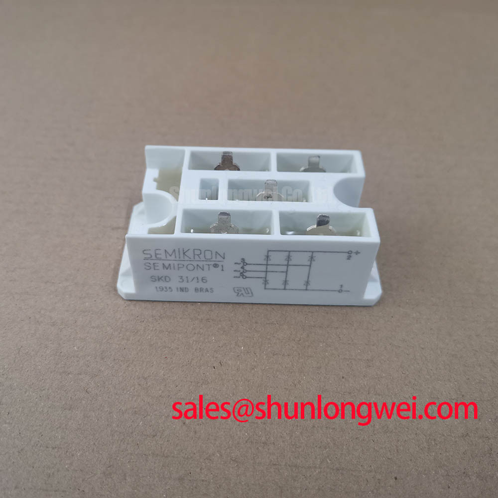
With the equipment isolated, first compare the installed unit’s terminal arrangement, Semipont housing condition, and cold-state diode readings with the circuit drawing before reconnecting the DC bus. The SKD53/16 is a Semikron bridge rectifier module in a Semipont package, rated at 1600.0 V and 53.0 A as Official Datasheet Specifications. These three identifiers are the primary electrical and mechanical boundaries for service evaluation; the original equipment documentation must still confirm terminal assignment, heatsink interface, fuse coordination, and the required rectifier topology.
| Manufacturer | Semikron |
| Product type | Bridge Rectifier Module |
| Rated voltage | 1600.0 V, Official Datasheet Specification |
| Rated current | 53.0 A, Official Datasheet Specification |
| Package | Semipont, Official Datasheet Specification |
The SKD53/16 is a bridge rectifier module, so a gate firing pulse, gate holding current, firing angle, and multi-pulse trigger train are not integration functions to assign to this part. Those controls apply to phase-controlled thyristor assemblies rather than a diode bridge module. During urgent maintenance, keeping that distinction clear prevents an incorrect troubleshooting path and avoids connecting a trigger circuit to terminals that belong to the rectifier power path.
Thermal inspection should instead begin at the practical locations where high-current rectifier failures often become visible: cable lugs, busbar contact faces, mounting hardware, heatsink flatness, and the thermal interface material. Discoloration, uneven contact marks, loose hardware, or a distorted Semipont housing can indicate that the complete mechanical path needs review. They do not, by themselves, establish the condition of the semiconductor junctions.
For a cold-state check, isolate surrounding capacitor banks and parallel paths where the equipment procedure permits, then compare each accessible diode direction with the circuit topology and a known-good signal path. An unexpected low-resistance path, an open path, or inconsistent readings between corresponding routes may indicate a module or connection issue. The technician should confirm the result after disconnecting external conductors because transformer windings, suppression networks, and downstream loads can alter an in-circuit reading.
⚠️ Field Alert: Tighten mounting and power-terminal hardware only to the original equipment or module documentation requirements, with a clean, evenly distributed thermal interface, because excess or uneven clamping force can damage the package or compromise heatsink contact.
Fuse selection requires the specific semiconductor fuse coordination information for the installed protection architecture. No fuse I²t value, mounting torque, or terminal-current allocation should be inferred from the stated 1600.0 V and 53.0 A ratings alone. This is a Design Consideration: verify the prospective fault current, transformer capability, conductor arrangement, and available coordination documentation before returning a high-current DC rectifier to service.
Transient Dynamics & Electrical Design: Phase-Controlled Rectification, Firing Angle on SKD53/16
A diode bridge based on the SKD53/16 does not provide adjustable DC output through a firing angle. Its rectification behavior follows the incoming AC waveform and the load network, while phase-angle control requires separate controllable semiconductor stages. If a cabinet schematic shows synchronizing transformers, pulse transformers, gate-drive boards, or an adjustable firing-angle controller, those functions should be traced to the appropriate thyristor or controlled rectifier section rather than attributed to this bridge module.
In a high-current green hydrogen electrolyzer DC power rectifier, engineers may evaluate a bridge module as part of the fixed rectification section feeding a larger DC regulation architecture. That evaluation must consider the actual transformer secondary voltage, line frequency, DC-link arrangement, reactor design, load current profile, and the control method used elsewhere in the system. The published 1600.0 V rating is an Official Datasheet Specification, but it is not a substitute for verifying repetitive operating voltage and measured transient peaks at the installed terminals.
AC-side waveform quality and reactive-power demand remain system-level concerns. Where phase-controlled equipment exists upstream or downstream, firing angle and conduction angle can affect harmonic content, transformer heating, and supply-side power factor. A diode bridge cannot correct those effects through a gate setting. Design Consideration: use recorded line current and voltage waveforms, together with the equipment’s control schematic, to identify whether distortion originates from the controlled stage, transformer saturation, load dynamics, commutation overlap, or an external supply issue.
When reviewing related Semipont parts for a repair bill of materials, the SKD 25/14 can be assessed as a separate rectifier-module reference for its own stated ratings and package details. It should not be treated as a direct replacement without confirming the electrical limits, mechanical fit, terminal layout, cooling arrangement, and circuit duty of the original installation.
Assembly Integrity & Layout Architecture: Implementing IEC 61000-4-5 Industrial Surge Immunity for SKD53/16
Surge protection for an SKD53/16 installation belongs to the complete AC input and DC output architecture. The commonly referenced surge-immunity document is IEC 61000-4-5; it is a system-level test standard, not a stand-alone certification claim for an individual bridge rectifier module. The module should not be described as independently compliant with an equipment-level surge or EMC requirement unless the relevant manufacturer documentation explicitly states that result.
Metal-oxide varistors, RC snubbers, input fuses, contactors, transformers, and line reactors each address different stress paths. Their selection depends on the nominal supply, earthing arrangement, transient source, transformer leakage behavior, enclosure wiring, and the measured voltage at the rectifier terminals. Engineering Recommendation: place protective functions so that the protected conductor loop is physically controlled and verify the resulting waveform at the module terminals under representative switching and load conditions.
The physical current path deserves the same attention as the protection components. Keep parallel conductors symmetric where the original design requires it, use clean mating surfaces, and prevent busbars from applying side load to the module terminals. Long, loose, or asymmetrical conductors can contribute to voltage excursions during current changes and can make a correctly rated module appear to be the root cause.
Semikron-Danfoss maintains an official power electronics and modules resource hub that can support broader product-family and application-document review. For equipment repair, the controlling reference remains the documentation matching the exact installed module and cabinet design.
SKD53/16 Operational Boundaries: Evaluating Critical Rate of Rise of Off-State Voltage Limits
Critical off-state voltage rise and unintended turn-on are thyristor-oriented concerns, not operating characteristics that should be assigned to a diode bridge module. The practical equivalent for the SKD53/16 is controlling switching transients and commutation-related stress across the rectifier terminals. A bridge can experience harmful voltage overshoot from transformer leakage inductance, DC-side current interruption, contactor action, poorly placed suppression components, or wiring inductance even when the steady-state supply appears acceptable.
RC snubbers and saturable reactors should therefore be treated as system-determined measures, not universal accessories with fixed values. Design Consideration: minimize the parasitic inductance of the power loop when suppressing commutation overshoot, then validate peak voltage against the DC-link and rectifier operating boundary during instrumented tests. Component values, resistor pulse capability, capacitor technology, and reactor characteristics must be selected from measured circuit behavior and the original engineering requirements.
For replacement evaluation, the important checks are the 1600.0 V rating, the 53.0 A rating, the Semipont enclosure, terminal configuration, cooling interface, and the actual topology of the equipment. A nearby model such as SKD82/18 can be reviewed as a separate family option, but interchangeability cannot be assumed from a similar product designation.
Where repeated rectifier distress is observed, capture AC input voltage, DC output ripple, terminal temperature behavior, and transient waveforms before changing surrounding protection parts. The IGBT Design & Integration technical resource provides useful system-level context for power-loop, thermal, and protection review, while the final corrective action must remain specific to the installed rectifier circuit.