




Content last revised on September 18, 2026
Field Diagnostics & Commissioning: AC to DC Transfer Characteristics across V in SKKT 20/14E Topologies
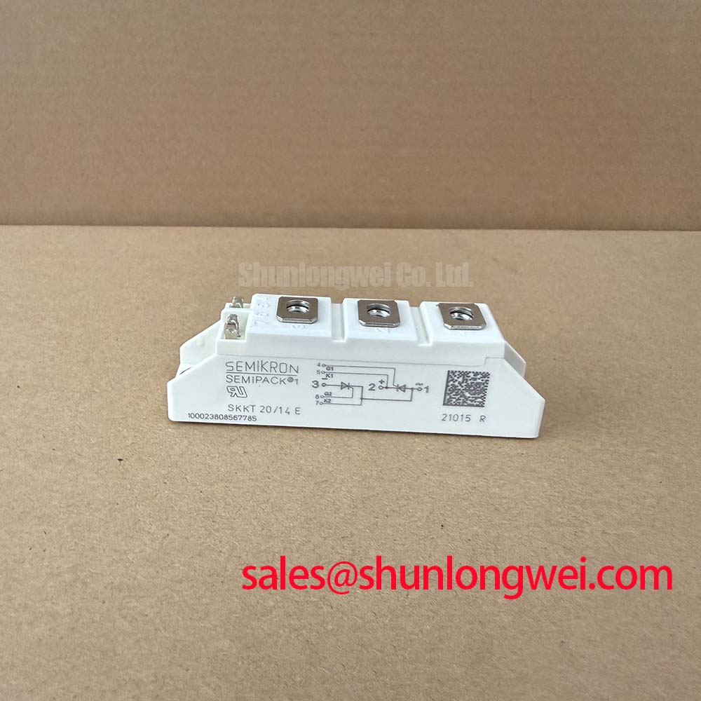
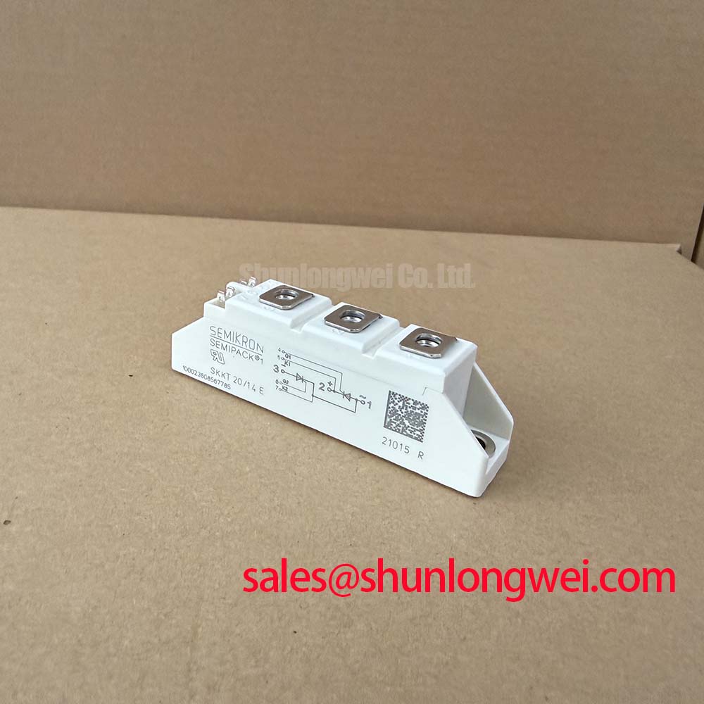
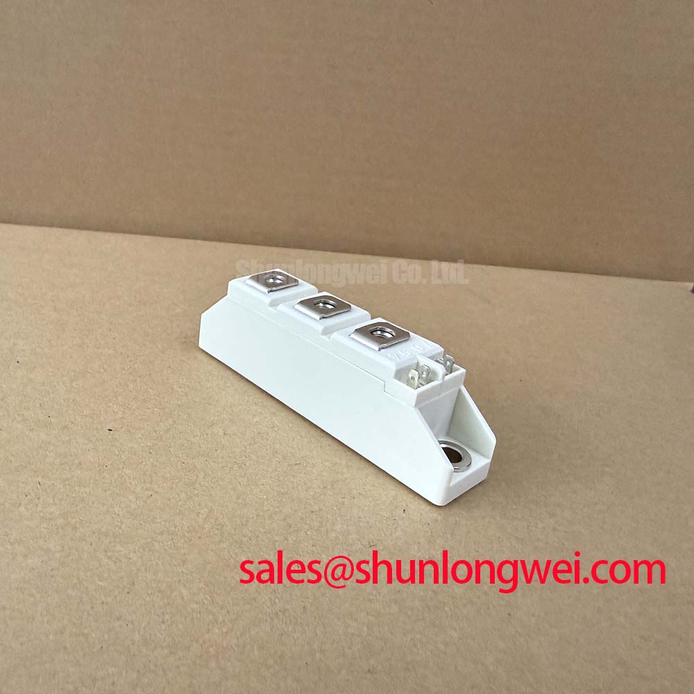
Begin service work by isolating the three phase supply, checking the module marking against the replacement record, and inspecting the case, terminals, and mounting surface for cracks, contamination, or signs of overheating. The Semikron SKKT 20/14E is a dual thyristor module specified for controlled power conversion, including evaluation in high voltage three phase motor solid state soft starter assemblies.
| Technical parameter | Official specification | Engineering significance |
|---|---|---|
| VDRM / VRRM | 1400 V | Repetitive peak blocking voltage for the thyristor paths |
| ITAV at Tc = 85°C | 20 A | Rated average on state current under the stated case temperature condition |
| ITSM at 10 ms and 25°C | 370 A | Non repetitive surge current reference for short duration events |
| (dv/dt)cr | 1000 V/µs | Critical rate of rise of off state voltage |
| Visol AC for 1 minute | 3000 V | Specified dielectric isolation test voltage |
| Rth(j-c) | 1.30°C/W | Thermal resistance from junction to case |
During commissioning, record the firing command, line voltage, load current, and heat sink temperature at several controlled firing angles. A phase controlled topology can produce a changing average output as the firing angle moves from early conduction toward late conduction, while the input current waveform becomes more discontinuous. This affects displacement power factor, reactive power demand, and harmonic current. The control system designer should evaluate these effects at the actual motor and supply impedance rather than treating the 20 A rating as a direct prediction of system input current.
The SKKT 20/14E carries an official VDRM / VRRM rating of 1400 V. This rating should be compared with the measured line to line voltage, transformer configuration, transient exposure, and the switching topology used in the soft starter. It is an electrical boundary for the module, not a substitute for system insulation coordination. For a 480 V class industrial line, the integrator should verify repetitive peak voltage and transient margin under normal operation, motor interruption, and upstream switching events.
Before energizing, confirm that the gate and main terminals are connected according to the Semikron mechanical and electrical documentation for the exact assembly. Measure continuity and insulation only with the module disconnected from control electronics and with the test method selected for semiconductor circuits. A cold resistance measurement is useful for identifying an obvious open or short condition, but it does not prove dynamic blocking performance. If a fault remains uncertain, compare waveforms with a known good phase and use an oscilloscope suitable for the voltage category.
The official ITAV rating is 20 A at Tc = 85°C. The actual current calculation must include conduction angle, load duty, enclosure temperature, heat sink performance, and any parallel path. Designers should also check the manufacturer’s fuse coordination and I2t data for the exact protection device. No fuse I2t value is stated here, so selection should not be based on the module’s 370 A surge figure alone.
When servicing an existing soft starter, inspect the heat sink contact area for dried thermal interface material, uneven seating, and restricted airflow. Check terminal tightness using the assembly manufacturer’s specified torque and calibrated tooling. Maintenance Note: isolate the equipment before terminal work, then monitor contact temperature and clean the heat sink and airflow path at the site’s preventive maintenance interval.
Transient Dynamics & Electrical Design: Coordination of Primary Spark Gaps, MOVs, on SKKT 20/14E
Protection around a thyristor module should be evaluated as a coordinated network. Primary surge arresting elements, MOVs, line fuses, and any RC snubber must be selected against the system’s prospective surge current, source impedance, repetition rate, and energy. The SKKT 20/14E specifies (dv/dt)cr = 1000 V/µs, but this number should not be interpreted as permission to omit external suppression. Wiring inductance and switching events can create local voltage conditions that differ from the panel measurement.
For mains surge evaluation, engineers may reference the principles described for surge protection. The cited industry reference helps frame the test method, but the complete assembly remains responsible for its own compliance evaluation. A discrete semiconductor module does not independently establish compliance with an equipment EMC standard.
Place the protection network with attention to the physical current loop. Keep the surge discharge path separate from sensitive gate wiring, minimize unnecessary conductor length, and verify the voltage appearing directly across the module during switching tests. The required MOV voltage class, energy rating, and quantity are system determined. The same applies to RC snubber resistance, capacitance, pulse capability, and damping behavior. These values should be selected from measured transient conditions and the manufacturer’s application data rather than copied from an unrelated soft starter.
The 3000 V AC isolation rating for 1 minute is an official dielectric specification for the module. It should be considered alongside the enclosure, heat sink mounting arrangement, contamination level, spacing, cable insulation, and production test procedure. Isolation testing can damage connected control circuitry, so the test boundary must be defined before applying a high voltage test.
When an MOV has operated repeatedly, inspect the complete protection branch, not only the semiconductor. Discoloration, cracked bodies, loosened terminals, or changes in leakage behavior may indicate that the protection network has experienced abnormal stress. Replace protective components according to the approved service procedure and repeat the relevant withstand and functional checks before returning the soft starter to service.
Preventing Spurious Faults: Preventing Localized Gate Hotspot Burnout Guidelines for SKKT 20/14E
Gate triggering should be examined at the module terminals, not only at the controller output. Long control wiring, poor reference routing, common impedance, electrical noise, and inadequate pulse energy can affect firing consistency. The exact gate trigger current, gate trigger voltage, latching current, and holding current must be taken from the applicable Semikron data for the production version being installed. They are not included in the supplied specification set and should not be inferred from the 20 A average current rating.
A practical commissioning method is to observe the gate to cathode waveform together with the main current waveform on each controlled path. Confirm that the pulse reaches the device at the intended electrical angle and that the load current establishes the expected conduction interval. If one phase behaves differently, inspect connector seating, gate return routing, control isolation, and the associated power circuit before attributing the condition to the module itself.
Pulse trains can be considered when the controller and the thyristor data permit them. The pulse strategy should be validated against gate power, repetition rate, synchronization accuracy, and immunity to commutation noise. Designers should avoid imposing a universal gate resistor or pulse current value without the official gate characteristic data. The correct starting point is the manufacturer’s trigger specification, followed by bench verification under the real gate wiring and temperature conditions.
Localized heating can also result from uneven current sharing in a parallel arrangement. Positive temperature behavior may assist static sharing in some semiconductor circuits, but it does not by itself guarantee dynamic sharing during the first part of a current pulse. If several devices are used in parallel, the busbar geometry, conductor resistance, gate timing, thermal coupling, and individual device characteristics should be reviewed together. A balanced layout and matched measurement points are more useful than assuming that equal physical appearance means equal current.
For service diagnosis, compare forward voltage, gate response, and thermal rise between phases under controlled low energy conditions before applying full motor power. An unusual waveform may indicate a control reference problem, impedance mismatch, commutation disturbance, or semiconductor damage. Verify the known good signal path with an oscilloscope and follow the site lockout procedure before changing the module.
SKKT 20/14E Operational Boundaries: Evaluating Post Surge Reverse Voltage Block Limits
The official ITSM rating is 370 A for a 10 ms half cycle at 25°C. This is a non repetitive surge reference, not a continuous overload allowance and not a guarantee that a downstream short circuit will leave the complete assembly undamaged. Fuse clearing time, source impedance, initial junction temperature, current waveform, and the physical protection layout determine the stress seen by the module.
After a surge event, disconnect the equipment and record the event condition before resetting the starter. Inspect the module body, mounting interface, terminals, fuses, MOVs, snubbers, busbars, and gate wiring. Test the blocking paths with an approved semiconductor test method and compare the readings with the corresponding phase. A device that passes a simple static check may still require controlled voltage and temperature testing before it is released for full duty.
The 1400 V repetitive peak blocking rating should be checked again before reverse voltage is reapplied. The review should include line voltage, commutation behavior, transformer leakage, motor regeneration, switching transients, and the condition of the surge protection network. The junction temperature cannot be established from ambient temperature alone; it depends on case temperature, current waveform, thermal resistance, mounting quality, and elapsed cooling time. The stated Rth(j-c) of 1.30°C/W is therefore an important input to the heat sink assessment, not a complete thermal design result.
For broader power semiconductor protection context, maintenance engineers can consult the practical discussion of Wide Bandgap Revolution when comparing switching behavior and transient control methods across semiconductor technologies. The SKKT 20/14E remains a silicon dual thyristor module, so its trigger, commutation, blocking, thermal, and protection checks must remain specific to its own documentation.
If a replacement is being considered, verify voltage class, average current, surge capability, terminal arrangement, mounting geometry, gate characteristics, thermal interface, and control compatibility as a complete set. The related SKKD46/04 may be evaluated as a separate product in a replacement study, but compatibility must be confirmed by the equipment designer rather than assumed from package similarity or brand association.