


Content last revised on September 21, 2026
Preventing Spurious Faults: Mechanical Mounting Torque Sequence and Thermal Guidelines for SKKT280/22EH4
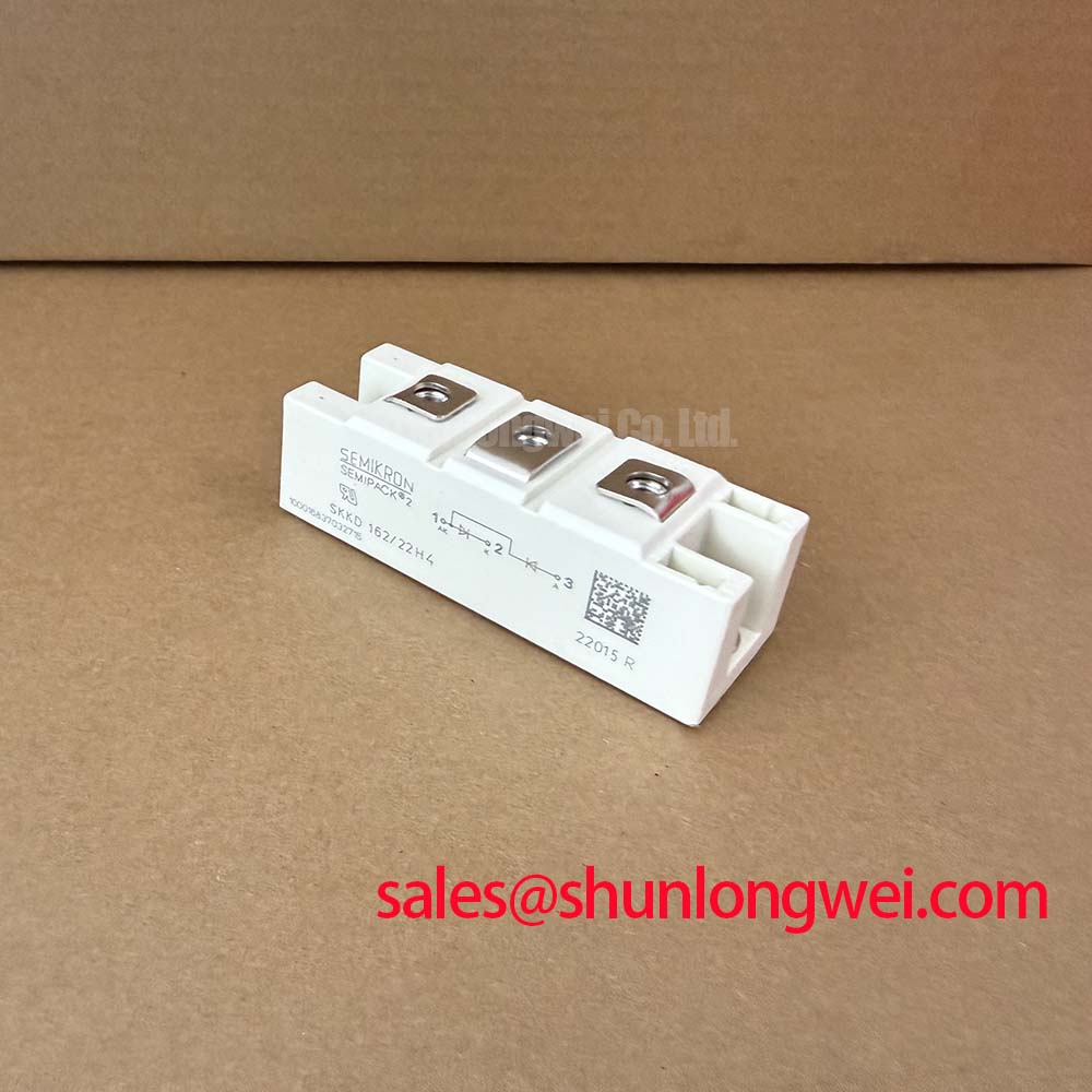
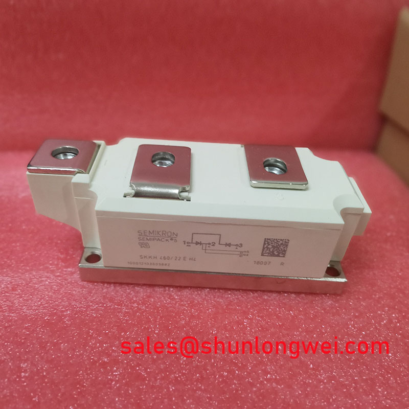
With the cabinet isolated and discharged, first inspect the SKKT280/22EH4 contact faces, terminal hardware, heatsink flatness, and thermal interface residue before reconnecting the power circuit. This Semikron thyristor module is officially specified with 2200 V VDRM/VRRM, 280 A IT(AV) at Tc = 85 C, 9100 A ITSM for 10 ms at 25 C, 0.11 K/W Rth(j-c), and 4800 V AC isolation voltage. These values define the module's electrical, surge, thermal, and isolation boundaries; they do not replace the verification of the surrounding fuse coordination, firing circuit, snubber network, busbar arrangement, and cooling path.
The device is a thyristor module for controlled high-current power paths. When assessing it for a grid-tied static var compensator or thyristor-switched capacitor equipment, technicians should compare the installed circuit function, voltage class, current duty, terminal arrangement, cooling interface, and gate-drive connection with the original equipment documentation. Electrical continuity checks with the equipment safely isolated can help identify an obvious short circuit or an open connection, but an in-circuit reading alone should not be treated as a complete functional assessment.
The official 0.11 K/W junction-to-case thermal resistance is relevant only when heat can pass consistently from the module case into a suitable heatsink. During replacement work, remove degraded thermal compound, clean both mating surfaces with an approved process, and inspect for burrs, corrosion residue, trapped debris, or uneven contact marks. A distorted mounting surface can create local thermal resistance that is not represented by the official junction-to-case rating.
Use the mounting hardware, tightening sequence, and torque value specified by the equipment maker or the applicable Semikron mechanical documentation. The supplied factory electrical data does not establish a mounting torque for this exact installation, so a specific value should not be assumed. As a Design Consideration, tighten opposing fasteners progressively in a balanced sequence so that contact pressure develops evenly across the baseplate. Confirm that the terminal lugs are clean, correctly positioned, and secured according to the original assembly specification.
Maintenance Note: Periodically monitor terminal and heatsink contact temperature during normal duty, then inspect blocked airflow, contaminated fins, and aging thermal interface material when an abnormal temperature rise is observed.
The official 9100 A, 10 ms surge on-state current rating describes a limited surge capability at 25 C; it must not be used as a routine operating-current target. In a service investigation after a downstream fault, review the protective-device coordination and the actual fault-clearing path. Fuse selection requires the fuse manufacturer's time-current and I2t information together with the equipment fault study. Where a fuse I2t coordination table is absent from the original design records, the responsible system engineer should validate the protective combination rather than infer adequacy from the module surge rating alone.
For an SVC or capacitor-switching assembly, accumulated dust and moisture can alter cooling and insulation conditions around the power stack. Keep the enclosure and forced-air route in the condition intended by the equipment manufacturer, and check for condensation evidence before returning a cabinet to energized service. The module's 4800 V AC isolation voltage is an official specified isolation test voltage; external creepage, clearance, enclosure contamination, and cable routing remain system-level responsibilities.
Assembly Integrity & Layout Architecture: Implementing Power Factor Degradation and Harmonic Mitigation for SKKT280/22EH4
A controlled thyristor power path changes the point in the AC waveform at which current is permitted to conduct. As firing angle moves away from the natural voltage crossing, displacement power factor and harmonic content can change with the connected reactor, capacitor bank, source impedance, and control strategy. This is a Design Consideration for the complete SVC or thyristor-switched capacitor system, not an individual performance specification of the SKKT280/22EH4.
During commissioning or fault investigation, compare the firing commands, phase reference, line-voltage waveform, and current waveform against the known-good equipment sequence. A shifted phase reference, inconsistent trigger path, loose power connection, or altered control setting can each affect the observed waveform. Engineers should use the installed system's harmonic limits, protection settings, and commissioning documentation to judge acceptable operation rather than applying a generic firing-angle prescription.
The module's 2200 V repetitive peak voltage rating provides an official voltage boundary, while the actual repetitive and transient stresses depend on the line network, capacitor switching events, commutation conditions, and physical power-loop layout. Minimize parasitic loop inductance to suppress inductive overshoots, then verify peak margins against the DC or AC circuit voltage during representative switching tests. The high-voltage concepts and measurement discipline discussed in The Ultimate IGBT Knowledge Base can be useful as general reference material, while the installed thyristor topology must remain the basis for acceptance decisions.
Where the equipment includes a separate front-end rectification stage, a module such as SKKD81/14 can be evaluated as a related topology element only after confirming its circuit role and ratings against the original design. It is not a declared replacement for the SKKT280/22EH4. Keep control wiring separated from high-current power conductors as required by the equipment layout, and inspect shield terminations and reference connections when waveform noise or irregular firing is present.
The IEC publication IEC 61000-4-2 Electrostatic Discharge Immunity provides system-level ESD immunity test context. It does not certify this individual power module as compliant with complete-equipment EMC or ESD requirements. Handle the gate-control connections using the plant's established ESD and isolation procedures to avoid introducing service-related damage into the firing assembly.
Assembly Integrity & Layout Architecture: Implementing Reverse Recovery Charge Considerations for SKKT280/22EH4
The SKKT280/22EH4 is identified here as a thyristor module. No diode reverse-recovery peak-current value, reverse-recovery time, softness factor, or reverse-recovery charge is included in the supplied official parameter set. Those diode-specific values must therefore not be assigned to this model. When the surrounding converter includes freewheel diodes, rectifier modules, or commutation capacitors, their own datasheets and measured waveforms determine reverse-recovery behavior.
In a thyristor-controlled capacitor-switching path, commutation behavior can still expose the module and adjoining parts to fast current transfer and voltage transients. An Engineering Recommendation is to inspect the actual commutation loop, measure voltage and current with appropriately rated instruments, and compare captured switching behavior with the known-good circuit. This helps distinguish a system-level commutation issue from a suspected module fault without claiming a single cause from one symptom.
Verify the polarity, physical routing, and termination quality of each power connection. A poor contact can contribute to local heating and transient behavior even when the semiconductor itself passes a basic cold test. The 280 A mean on-state current rating at Tc = 85 C is the official continuous-current reference under its stated case-temperature condition. It should be evaluated with the actual heatsink, ambient environment, duty cycle, and waveform of the installed assembly.
When an alternative within the same product family is being reviewed during maintenance planning, SKKT 250/14E provides a neutral comparison point. A valid cross-reference requires review of voltage rating, current rating, isolation requirements, terminal geometry, gate characteristics, thermal interface, and the original circuit documentation. Similar naming or package appearance is insufficient evidence of functional interchangeability.
Preventing Spurious Faults: Gate Trigger Current Temperature Dependence Guidelines for SKKT280/22EH4
Gate triggering should be assessed at the firing circuit, not inferred from the module's main-current ratings. The supplied official data set does not state gate trigger current, gate trigger voltage, holding current, latching current, allowable gate-pulse rise time, or a temperature dependency curve for the SKKT280/22EH4. These values must be obtained from the applicable manufacturer documentation before modifying a gate-driver board, changing a pulse transformer, or setting a firing threshold.
As a Design Consideration, inspect the gate and cathode wiring for correct identification, secure connection, contamination, and damage before energizing the cabinet. Confirm that the firing pulse reaches the intended device under the actual equipment sequence and that the trigger reference is consistent across phases. A missing or degraded pulse can coexist with an otherwise normal static resistance reading, while irregular triggering can arise from several conditions in the controller, wiring, synchronization circuit, or power stage.
Temperature can affect semiconductor triggering behavior and the overall firing margin of the installed assembly. When investigating intermittent operation after warm-up or in a cold enclosure, compare gate-drive waveforms and line synchronization at different stable operating temperatures under approved test conditions. Designers should verify that the original control board maintains the required triggering conditions across the equipment's specified environmental range, rather than applying unverified universal drive values.
For preventive maintenance, retain baseline waveform records from a known-good unit where plant procedures permit. Recheck terminal tightness, cooling performance, moisture control, and gate-drive integrity during scheduled shutdowns. These practical checks support the service life of the complete power assembly without claiming a particular lifetime, failure rate, EMC result, or system certification for the module.