
Content last revised on October 7, 2026
SKM195GB063DN Operating Boundaries and DC Bus Voltage
| Model | SKM195GB063DN |
|---|---|
| Manufacturer | Semikron |
| Product category | IGBT module |
| Package | Semitrans (Official Specification) |
| Rated voltage | 600 V (Official Specification) |
| Rated current | 195 A (Official Specification) |
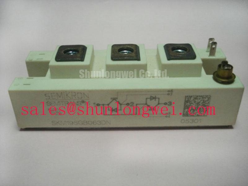
Measure the discharged DC bus and inspect the failed switch position before evaluating a SKM195GB063DN replacement. Record the drive nameplate, the module markings and any evidence of arcing at the power terminals. The module’s 600 V rating is an Official Specification; it is not the permissible steady DC bus voltage for every installation. During commissioning, capture the voltage at the module terminals, including switching overshoot, and assess the result against the applicable device documentation and the drive’s operating conditions.
For a heavy-duty variable frequency AC motor drive, check what feeds the DC link as well as what the inverter switches. A change in input supply or rectifier operation can alter bus voltage before any gate command reaches the IGBT. If the equipment uses phase-controlled rectification, examine the firing controls and input waveforms rather than assuming an inverter fault explains an abnormal bus reading. Harmonics are a system-level concern: Fourier series provides the analytical basis for separating periodic waveforms into harmonic components, but the appropriate mitigation depends on measurements at the installed equipment.
Design Consideration: cosmic-ray-related single-event burnout risk can matter when assessing semiconductor voltage stress, particularly where installation conditions differ from the original equipment design. No device-specific failure rate, altitude limit or voltage derating curve is established by the specifications on this page. Do not calculate a FIT figure or declare a safe operating altitude from the 600 V rating alone. Instead, document the site conditions, bus-voltage history and switching peaks, then obtain the relevant manufacturer reliability data if the project requires a quantified assessment. The broader Industrial Applications guide is context for system-level reliability review, not a substitute for model-specific limits.
Inspect spacing around the installed terminals while the assembly is isolated. Dust, conductive residue, displaced insulation and altered busbar alignment deserve attention even when a cold meter test finds no short. Creepage and clearance must be assessed against the equipment’s insulation design and operating environment; the module’s voltage rating alone does not define an installation-wide spacing rule.
Transient Dynamics and Current Distribution at SKM195GB063DN
Compare cold collector-to-emitter and gate-to-emitter readings with an undamaged position in the same equipment, using the same meter range and lead placement. A low reading can warrant further investigation, but a single resistance or diode-mode result does not identify the failed component by itself: connected snubbers, gate-drive circuitry and parallel paths can affect the measurement. Isolate connections as the service procedure permits, and trace each terminal against the original schematic before fitting a module.
The 195 A current rating is an Official Specification, not a guarantee that parallel devices will share current evenly. Design Consideration: static sharing depends on device characteristics at the actual operating temperature, while dynamic sharing also depends on gate-drive timing, gate-loop impedance and power-path symmetry. Do not assume a favourable temperature coefficient over every current and temperature condition without the relevant device curves. If the equipment uses parallel switch positions, compare their wiring, fastening and drive waveforms before attributing unequal heating to one module.
Keep gate and emitter connections consistent with the equipment drawing. During a controlled switching test, compare turn-on and turn-off waveforms at equivalent positions, using suitable probing practice. A timing difference may point to the driver, its supply, a connection or a device characteristic; follow the evidence rather than changing gate components to compensate for an unidentified fault. Check driver-supply behaviour under repeated switching, including any bootstrap supply used by the original design. Its recharge path, capacitor behaviour and diode recovery need evaluation under the equipment’s duty cycle, with component values determined by that design.
Alternative-module searches require the same discipline. SKM100GB063D is another Semikron model to compare during a replacement evaluation, not a verified direct substitute for SKM195GB063DN. Compare ratings, terminal arrangement, mounting and drive requirements before making a compatibility decision. The same applies to SKM75GB07E3 when reviewing devices elsewhere in a drive topology; its presence in a parts search does not establish an interchangeable role. Semikron-Danfoss describes broader module and integration concepts in its SKiiP technology information, which should not be mistaken for a specification of this Semitrans module.
Field Diagnostics and the Thermal Interface
Inspect the heatsink contact area and module seating when a switch position runs hotter than comparable positions. Look for uneven interface-material transfer, contamination, raised fastener areas and evidence that the module was pulled down unevenly. A thermal image taken under a repeatable load can help locate a temperature difference, but it cannot, by itself, distinguish interface contact from switching loss, cooling-flow or current-sharing problems.
Design Consideration: apply thermal interface material as a continuous, controlled layer suited to the selected material and the equipment’s mounting instructions. Excess material can impede heat transfer; gaps can leave parts of the contact area poorly coupled. No material thickness or tightening torque is specified here as an Official Specification for SKM195GB063DN. Check heatsink flatness, module seating and the specified fastener procedure rather than using a generic number to compensate for visible distortion. Tighten progressively in the sequence required by the equipment or applicable module documentation, then inspect for displaced material at the edges.
Field Alert: Isolate and verify the DC link is discharged before loosening module terminals or disturbing the thermal mounting.
After reassembly, confirm that terminal hardware is secure and busbars sit without forcing the module into position. On equipment exposed to vibration, inspect supports and joint condition as part of the fault investigation; a loose electrical joint can create local heating that resembles a cooling problem. Recheck electrical isolation and the gate connections before a controlled run. Log the cooling conditions, load and temperatures so a later comparison reflects the same operating point. If heating persists, review measured switching behaviour and the cooling path rather than adding more interface material without evidence.
Motor Lead Reflections and Practical Switching Checks
Probe the module terminal voltage during controlled switching if failures recur after a motor cable or output-stage change. Compare the measured peak with the DC bus at that moment and with the device’s 600 V Official Specification. Use an instrument and probe arrangement appropriate to the circuit; lead placement and measurement bandwidth can otherwise make a transient appear smaller or larger than it is. Keep the equipment’s approved protection and test procedures in place throughout the check.
Design Consideration: long motor leads can support reflected voltage waves when cable and load impedances are mismatched. That mechanism can raise stress at the motor terminals, while module-terminal stress must be measured at the module rather than inferred from a motor-end reading. Cable construction, length, switching edge and termination all affect the result. Do not assume a fixed spike multiplier or prescribe a filter from cable length alone. Compare waveforms at the points relevant to the reported fault, then let the system engineer assess an output filter or choke against motor insulation, drive operation and the measured switching conditions.
At the module, minimize avoidable power-loop inductance when reviewing replacement busbar routing, because turn-off current changes can produce additional terminal overshoot. Preserve the original layout where it is serviceable, and investigate altered joints or displaced conductors before changing component values. Confirm any proposed routing or output-stage change by measuring peak voltage under the equipment’s relevant operating conditions. A waveform that improves at one load point does not establish adequate margin across the drive’s full duty cycle.
If the voltage trace is clean but the drive still trips, move through the signal chain: compare gate commands, driver-supply behaviour, current feedback and the recorded fault timing. A trip coinciding with switching may indicate several possible paths, including sensing or protection activity, rather than an IGBT defect. Record the observations alongside the module marking, Semitrans package fit and terminal arrangement so the repair decision rests on both electrical evidence and physical compatibility.