




Content last revised on September 10, 2026
Field Diagnostics & Commissioning: Derating Guidelines and Mismatched Parameters in SKM22GD123D Topologies
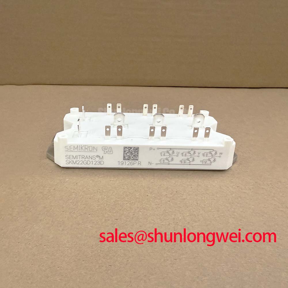
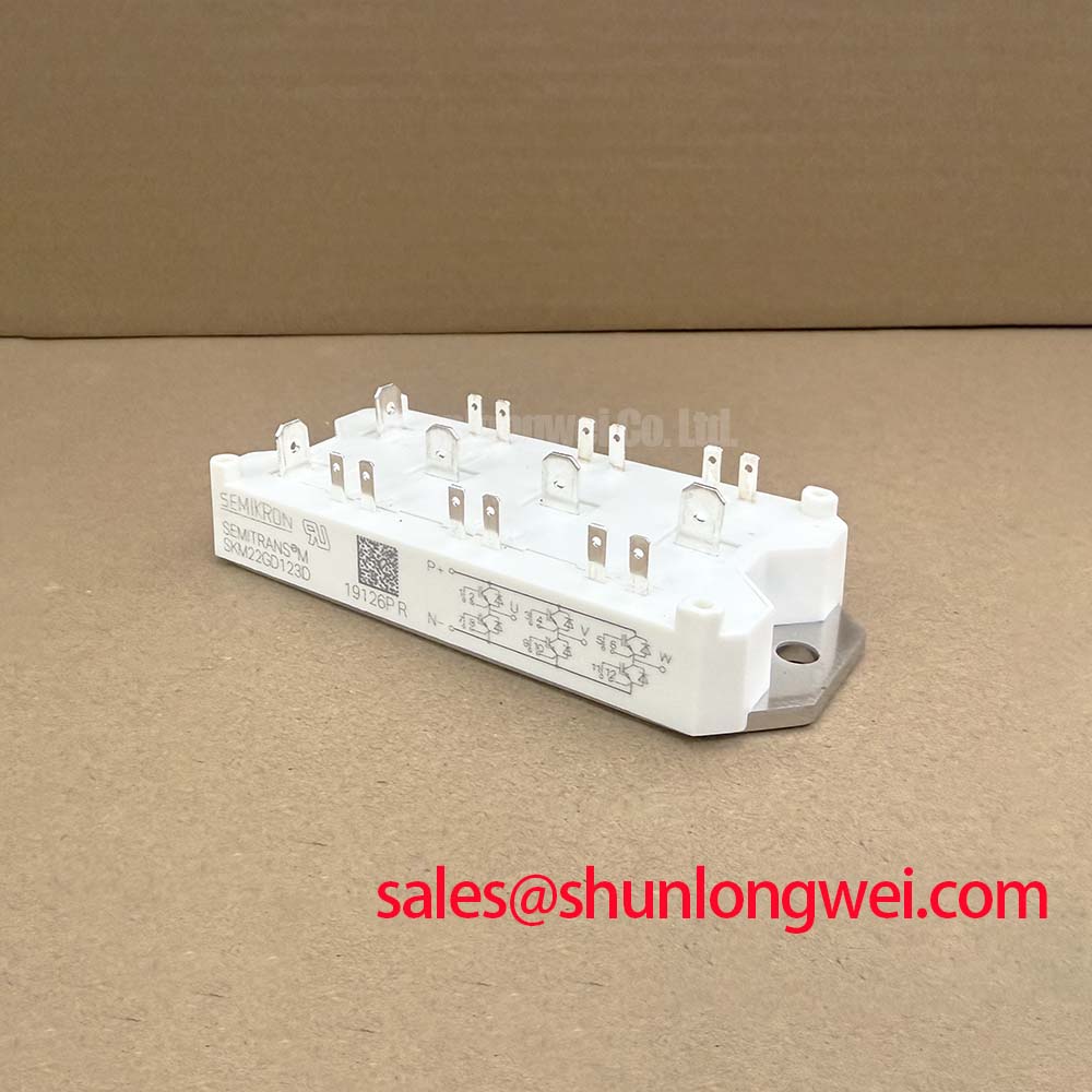
With the drive cabinet isolated, first compare the cold state terminal relationships and gate related readings of the SKM22GD123D against the original circuit documentation before reconnecting any control wiring. This Semikron power module has a specified 1200 V voltage rating and a 22 A rated-current value, supplied in the Semitrans housing. The applicable datasheet conditions govern how these ratings should be interpreted during incoming inspection, repair assessment, and equipment recommissioning.
| Parameter | Official Specification |
|---|---|
| Product model | SKM22GD123D |
| Manufacturer | Semikron |
| Voltage rating | 1200 V |
| Current rating | 22 A, subject to the applicable datasheet conditions |
| Housing | Semitrans |
Before fitting an SKM22GD123D into a repaired converter, confirm that its voltage and current ratings match the original design record rather than relying on a visual package match. The 1200 V and 22 A values define the module’s published rating class, but they do not independently establish the allowable switching frequency, cooling capability, overload profile, or DC link operating point of a particular machine.
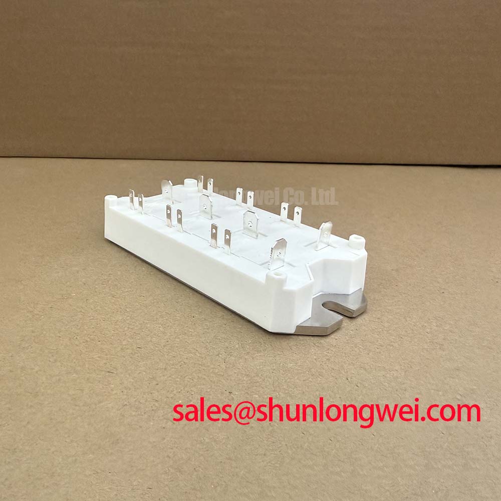
For incoming checks, inspect the Semitrans case, terminal hardware, mounting surfaces, and marking condition for handling damage that could affect electrical contact or heatsink coupling. With the module disconnected from the surrounding circuit, use a diode test function only as a comparative screening method. Readings should be compared between equivalent paths and, where possible, against a known good unit from the same equipment. An unexpected low resistance path, an inconsistent directional diode reading, or an apparent gate related short can justify further controlled testing, but a multimeter result alone does not identify a root cause.
In parallel current paths, the positive temperature coefficient associated with IGBT on state voltage can support steady state current sharing under appropriate conditions. This is a Design Consideration, not a guarantee that unmatched modules will share switching current equally. Dynamic imbalance can still arise from unequal gate wiring, unequal driver timing, dissimilar commutation loops, or differing thermal conditions. Keep corresponding gate drive paths physically symmetrical where the system topology uses parallel devices, then verify turn on and turn off waveforms under controlled load conditions.
Equipment repair teams assessing light industrial automation or multi joint robotic articulator drives should also check the motor cable route and output network. Long motor leads can create reflected voltage events at the motor terminals. Designers should evaluate the cable, motor insulation system, output filter arrangement, and measured switching waveform together rather than applying a generic cable length limit. The system engineer should verify peak voltage margins against the actual DC link voltage during switching tests.
💡 Bench Tip: Keep gate terminals protected from electrostatic handling and record cold state comparison readings before energizing a replacement module.
For a broader reference on where power modules are evaluated across industrial energy conversion equipment, see this Industrial Applications engineering guide. It is useful context when separating an observed system level fault from the electrical limits published for the module itself.
Field Diagnostics & Commissioning: High dv/dt Cross Conduction Shoot Through in SKM22GD123D Topologies
A gate waveform that rises when its associated device should remain off may indicate capacitive coupling through the power stage, shared return inductance, inadequate driver immunity, or probe connection error. In a switching bridge, this condition can contribute to cross conduction and a rapidly increasing DC link current. Investigate it with isolated measurement methods and compare the suspect gate waveform with the driver output and the local emitter reference used by the existing design.
Active Miller clamping and negative gate bias are commonly considered by drive designers when a topology must resist dv/dt induced turn on. These are Engineering Recommendations whose suitability depends on the installed gate driver, the original gate voltage limits, insulation arrangement, control timing, and measured switching behavior. Do not impose a gate bias value from a general rule. The system integrator should verify the required gate drive conditions from the original equipment documentation and controlled waveform tests.
Gate loop routing should minimize shared inductance between the power current loop and the driver return path, particularly during turn off. Where an auxiliary emitter connection is provided by the original circuit arrangement, keep its sensing path separate from high current emitter conductors to reduce voltage error at the driver reference. This is a layout principle intended to suppress unwanted gate movement; final routing effectiveness must be confirmed at the installed switching current and bus voltage.
When the equipment includes high speed semiconductor fuses, verify coordination using the fuse manufacturer’s published clearing information, the converter fault energy conditions, and the system protection study. Fuse I²t data cannot be compared directly with an unspecified module surge capability. Rapid fault isolation depends on the complete path, including DC link impedance, contactors, busbars, driver protection response, and the fault location.
The softness of freewheel diode reverse recovery can influence current transition shape and conducted or radiated noise in a complete converter. Oscilloscope measurements should assess the real commutation loop and probe arrangement before attributing EMI or overvoltage to the module. For housing and product family context, Semikron Danfoss describes SEMITRANS® industry standard IGBTs within its power module portfolio.
Benchtop Waveform Tuning: Mitigating Stress via Junction to Case Thermal Network Simulation on SKM22GD123D
Thermal assessment starts by separating average power loss from short duration pulse loading. The official rating of 22 A does not provide a universal overload allowance for a robotic axis, actuator supply, or automation drive. Pulse duration, repetition, switching loss, case temperature, heatsink behavior, and cooling conditions all change the junction response.
A junction to case transient thermal model can help a system engineer estimate whether a particular pulsed workload produces an acceptable peak junction temperature. In practice, the model should use device specific thermal data from the applicable manufacturer documentation and be correlated with measured case temperature and electrical waveforms. Multi RC networks are useful because heating does not transfer through the module at a single fixed rate. They should not be replaced with a steady state thermal resistance assumption during repeated acceleration or regenerative events.
During bench commissioning, capture collector current, collector emitter voltage, gate voltage, and case temperature in the same operating sequence. A rising temperature trend may reflect increased conduction loss, switching loss, restricted cooling, an uneven mounting interface, or altered control behavior. Review these factors as a group. Avoid assigning the condition to one cause until the gate waveform, load current, cooling path, and mechanical installation have been checked.
Bidirectional DC DC battery charging and discharging systems can impose repeated thermal cycling when their operating profile alternates power direction. This is a Design Consideration for the complete converter rather than a lifetime claim for the SKM22GD123D. The equipment designer should evaluate the actual load cycle, cooling control, and switching sequence with the applicable device documentation and qualification requirements.
If a repair assessment identifies a need to compare rating classes, the SKM100GB063D is a separate Semikron module reference that should be evaluated only against the original topology, pin arrangement, voltage class, current demand, gate driver compatibility, cooling interface, and protection design. A model number similarity or shared manufacturer does not establish interchangeability.
Benchtop Waveform Tuning: Mitigating Stress via Baseplate Convexity Compensation and Screw Control on SKM22GD123D
Before mounting the Semitrans package, clean the heatsink contact area and inspect it for residue, burrs, dents, and localized high points. The mounting interface must provide even thermal contact without forcing the module body into distortion. If the original service procedure specifies a thermal interface material, use the documented material type and application method. Interface thickness, flatness, and void control affect the thermal path, so these items should be verified rather than assumed from visual appearance.
Baseplate curvature and heatsink flatness can change contact pressure across the mounting area. A suitable installation process uses an even screw tightening sequence that progressively seats the package rather than loading one corner first. The correct fastener torque is system and hardware dependent. Follow the original equipment service documentation or the applicable manufacturer mounting instruction, and use calibrated tooling where the repair process requires controlled torque.
After installation, inspect terminal alignment and ensure that busbar contact surfaces sit flat without mechanical preload from cable routing. Excessive busbar force can transfer stress into terminals and alter connection resistance over time. Verify terminal tightening against the equipment documentation, then perform continuity checks before applying power.
During controlled startup, begin with the equipment’s prescribed low risk commissioning mode if available. Observe DC link behavior, output current balance, gate signals, and heatsink temperature response before permitting normal motion commands. For multi joint robotic articulators, confirm that axis acceleration, braking, and regenerative operating states are tested individually as well as in combined motion sequences, because the converter duty can differ significantly between those conditions.