

Content last revised on October 6, 2026
Preventing Spurious Faults: Evaluating Thermal Capacitance and Heat-Sink Response for SKM400GA128D
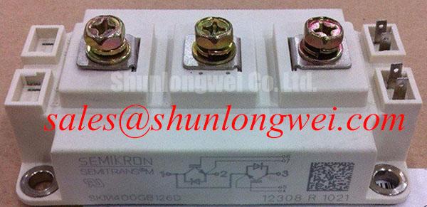
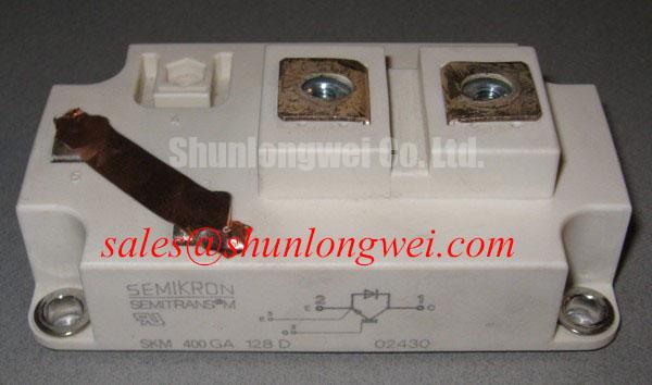
Begin a service inspection by confirming the module marking, checking the external housing for cracks or deformation, and comparing the installed device with the equipment documentation before applying power. The SKM400GA128D is a Semikron IGBT module with an official rated voltage of 1200 V, an official rated current of 400 A, and a Semitrans package. These values define the component identity and rating boundary; they do not by themselves establish the permissible current for every switching frequency, duty cycle, ambient condition, or cooling arrangement.
For a traction inverter evaluation, engineers should first reconstruct the actual electrical and thermal operating envelope. Record the DC-link voltage, switching pattern, load profile, gate-drive timing, cooling medium, heat-sink temperature, and enclosure conditions. A short overload pulse can be limited by semiconductor junction heating, while a longer event is strongly influenced by the heat sink, mounting interface, cooling path, and thermal capacitance of the complete assembly. The transient response should therefore be evaluated with the manufacturer’s available thermal impedance data and a system-level RC thermal model rather than by using the 400 A rating as a continuous operating prescription.
A practical model separates the junction-to-case path from the case-to-heat-sink and heat-sink-to-ambient paths. The first path governs the early temperature response during a switching burst; the external assembly becomes increasingly important as the pulse continues. Engineers can compare the calculated junction-temperature rise with measured case temperature and switching-waveform data. If the calculated and measured trends disagree, inspect the thermal interface, clamping condition, sensor position, cooling flow, and current waveform before assigning the fault to the module.
Thermal capacitance also affects repeated acceleration and braking events. A traction inverter may experience several different pulse durations within one operating cycle, so a single steady-state heat-sink temperature is insufficient for validation. Use the actual duty sequence in the thermal model, then verify the result with thermocouples or other suitable sensors placed at repeatable locations. The final temperature margin remains a system-design result and should be verified under the intended enclosure, airflow, and control conditions.
For background on power-module construction and system integration, engineers can consult IGBT Design & Integration. The Semitrans family is also described in the Semikron-Danfoss SEMITRANS® Industry Standard IGBTs reference area.
SKM400GA128D Thermal-Electrical Optimization: Suppressing Cres-Induced Gate-Voltage Spikes
During bench testing, monitor the gate-emitter voltage and collector-emitter waveform at the module terminals with a measurement setup designed to minimize probe-loop error. A fast collector-voltage transition can couple through device capacitances and the physical commutation path into the gate circuit. The resulting gate disturbance may appear as an unwanted turn-on tendency, abnormal switching loss, or cross-conduction risk in a bridge leg. These observations should be treated as diagnostic clues, not as proof of a single failed component.
A suitable design consideration is to keep the gate-drive return path tightly controlled and physically separated from high-current commutation paths. The driver supply decoupling, gate resistor arrangement, protection circuit, and signal reference should be evaluated as one loop. If the system uses an active Miller clamp, its effectiveness depends on driver architecture, propagation delay, layout impedance, and the measured gate waveform. A negative gate-bias strategy can also be considered where the selected driver and the complete module gate specification permit it, but the actual bias value must be taken from the applicable driver and module documentation rather than assumed from general IGBT practice.
Parallel-module operation requires additional verification. Static current sharing is affected by electrical symmetry, connection resistance, stray inductance, gate-drive matching, thermal coupling, and the temperature dependence of the individual devices. A positive temperature coefficient of conduction voltage can support current-sharing behavior in some operating regions, but it is not a substitute for matched layout and measured dynamic performance. Use symmetrical busbar geometry, equalized gate-drive paths, and a common measurement method, then compare each module’s switching voltage, gate waveform, and case temperature under the same test sequence.
When selecting a different current class for a separate branch or a lower-power assembly, the SKM100GB063D should be evaluated only against the original circuit requirements and its own official documentation. Its presence in the same product family does not make it an automatic substitute for the SKM400GA128D. Check voltage class, current requirement, topology, gate characteristics, mechanical compatibility, thermal path, and protection coordination before any replacement decision.
💡 Pro Tip: Use a symmetrical laminated busbar and validate turn-off overshoot, gate disturbance, and device temperature with a double-pulse or equivalent switching test before approving the traction inverter layout.
Preventing Spurious Faults: Reinforced Insulation Barrier Integrity and Isolation Verification
The isolation interface around a high-voltage IGBT module must be assessed as part of the complete converter, not inferred from the module voltage rating. The official 1200 V rating of the SKM400GA128D describes its electrical switching class; it does not independently certify the reinforced insulation system of a locomotive traction inverter. Clearance, creepage, contamination, enclosure geometry, cable routing, connector selection, monitoring circuits, and protective barriers all contribute to the final isolation result.
Before energizing a repaired assembly, inspect the module mounting area, insulating interface, busbar edges, driver isolation barrier, and nearby fasteners. Remove conductive debris and confirm that the mechanical installation has not displaced an insulating sheet or introduced a sharp edge near the high-voltage path. Any insulation-resistance or withstand test must follow the equipment manufacturer’s approved procedure, test voltage, duration, discharge method, and safety controls. Do not infer a pass or fail threshold from the module’s 1200 V switching rating.
Common-mode transient immunity is similarly a system property. A high dv/dt event can couple through transformer capacitance, isolated power supplies, digital isolators, shield structures, and gate-driver reference paths. If a gate signal appears unstable during switching, compare the isolated command signal with the local gate-emitter waveform using appropriately rated instrumentation. Check driver supply stability, isolation power return currents, propagation timing, and the physical route of control wiring. The system designer must establish the required immunity level from the converter’s switching conditions and verify it with a controlled test; no specific CMTI value is an official parameter supplied here for this module.
For packaging context, Semikron describes its sintering technology in the Semikron Sintering Technology reference material. That technical background should not be interpreted as a complete insulation or safety certification for a repaired inverter. The finished equipment still requires its own validation against the applicable railway, industrial, electrical safety, and EMC requirements.
Benchtop Waveform Tuning: Mitigating Stress Through Baseplate Contact and Mounting Control
Before waveform tuning, confirm that the module baseplate is seated on a clean, flat heat-sink surface and that the thermal interface material has been applied consistently. Uneven contact can create local thermal resistance and may also alter mechanical stress on the package. Inspect the heat-sink surface, mounting holes, insulating parts, and contact pattern. If the assembly uses an electrically insulating interface, verify its dielectric and thermal suitability from the system documentation rather than assuming that any commercially available pad or compound is compatible.
Thermal interface thickness should be controlled according to the selected material supplier’s process guidance. Excess material can increase thermal resistance, while insufficient coverage can leave voids or dry regions. The correct application method depends on the material, surface finish, flatness, and clamping system. Baseplate flatness and any convexity should be checked with suitable workshop metrology when abnormal temperature spread persists after electrical checks.
Mounting screws should be tightened progressively in a crosswise sequence so that the baseplate approaches the heat sink evenly. The applicable torque must come from the Semikron mechanical documentation, the fastener specification, and the heat-sink assembly design; a generic torque value should not be presented as an official SKM400GA128D requirement. After mounting, inspect the contact imprint where practical and repeat the thermal test under the same load profile used before servicing.
Bench Diagnostic: Disconnect all power sources and allow the DC link to discharge before inserting or removing gate-drive, sensing, or power connections.
Waveform tuning should then proceed with a controlled change to one variable at a time, such as gate resistance, driver timing, busbar arrangement, or snubber configuration. Record collector-emitter voltage, gate-emitter voltage, current commutation, case temperature, and fault signals together. If the waveform changes after remounting, compare the electrical records with the thermal-interface and clamping inspection rather than assigning the change to gate-drive tuning alone. The approved operating point must be established by the equipment designer through measured voltage, current, temperature, and protection margins.