Content last revised on September 1, 2026
Differential Gate-Source Loop Routing to Suppress Ground-Bounce Noise
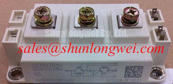
In utility-scale wind power converters operating under fluctuating aerodynamic loads, high current slew rates during switching transitions routinely exceed thousands of amperes per microsecond. The SKM400GB126D half-bridge module is built in the standard Semikron-Danfoss SEMITRANS® Industry Standard IGBTs housing, rated at a collector-emitter voltage of 1200V and a continuous collector current of 400A at standard case temperatures (Official Datasheet Specification). When routing gate driver signals in multi-megawatt nacelle converter stacks, the primary vulnerability to spurious switching is mutual inductive coupling between the main emitter power return and the auxiliary control emitter trace.
Main emitter terminals carry the full phase current, which introduces inductive voltage drops across internal wire bonds and terminal leads during rapid turn-off. If a single common conductor is shared between the power circuit and the gate driver return, this ground bounce directly injects a differential voltage transient into the gate-emitter junction. To decouple these circuits, auxiliary Kelvin emitter terminals must be routed strictly as dedicated differential pairs back to the driver stage. A recommended physical trace separation of at least 8 mm from high-current AC busbar runs (Design Consideration) prevents capacitive and magnetic cross-coupling.
| Engineering Parameter | Specification / Guideline | Engineering Category |
|---|---|---|
| Collector-Emitter Breakdown Voltage (VCES) | 1200 V | Official Datasheet Specification |
| Continuous Collector Current (IC @ Tc = 80°C) | 400 A | Official Datasheet Specification |
| Gate Driver PCB Differential Loop Inductance | < 15 nH | Design Consideration |
| Recommended Gate Resistance Starting Value (RG(on) / RG(off)) | 2.0 Ω to 4.7 Ω | Typical Starting Point |
When bench-testing lower-power sub-assemblies or auxiliary crowbar channels within the turbine converter, plant technicians frequently cross-reference the scaled-down SKM100GB124D to verify gate driver timing protocols before qualifying 400A stages. Keeping the gate-emitter loop area below 2 cm² by utilizing tightly twisted pairs or multi-layer PCB inner ground planes suppresses radiated electromagnetic interference from nearby switching nodes.
Active Miller Clamp Implementation & Parasitic Capacitive Turn-On Prevention
Phase-leg topologies in grid-tied wind converters subject the idle IGBT to severe voltage transients (dv/dt) whenever the complementary switch turns on. The rapid rise in collector-emitter voltage pulls current through the internal gate-collector Miller capacitance (Cres). If this displacement current develops a voltage drop across the off-state gate resistor that exceeds the module's threshold voltage (typically 5.0V to 6.5V, Official Datasheet Specification), an unintended parasitic turn-on occurs, precipitating catastrophic DC-bus shoot-through.
Implementing an active Miller clamp circuit provides an ultra-low impedance sink path directly at the module gate terminal. Once the gate discharge voltage drops below an internal threshold (commonly calibrated around +2.0V), a dedicated clamp MOSFET shorts the gate directly to the negative auxiliary rail, effectively bypassing the external turn-off gate resistor. While operating with a symmetrical or asymmetrical negative gate bias (-8V to -15V) offers high noise immunity, active clamping minimizes negative supply power consumption while preventing cross-conduction under dv/dt rates exceeding 15 kV/µs.
⚠️ Maintenance Note: During scheduled major overhauls (recommended at 24- to 36-month intervals in offshore environments), thermal interface material (TIM) degrades through mechanical pump-out and solvent evaporation. Inspect the baseplate contact footprint using a thermal imaging camera under rated inverter load. Any localized delta exceeding 12°C between adjacent modules indicates dried thermal grease or improper bolt torque.
When remounting the SKM400GB126D onto liquid-cooled aluminum cold plates, adhere strictly to a uniform thermal paste thickness of 50 µm to 80 µm applied via stencil printing (Design Consideration). Fasten the baseplate M6/M5 mounting bolts in a diagonal, cross-pattern sequence. Initial pre-tightening must not exceed 2.0 N·m, followed by a final calibrated torque of 3.0 to 5.0 N·m (Official Datasheet Specification) to avoid ceramic substrate warping or DCB copper layer fracture.
Calculating Failures-in-Time (FIT) Rates in High-Altitude Solar and Wind Farms
Wind turbines and utility-scale solar farms installed in plateau or alpine regions (>2,000 meters above sea level) experience significantly higher terrestrial cosmic ray neutron fluxes compared to sea-level installations. High-energy atmospheric neutrons colliding with the silicon lattice within the blocking junction generate electron-hole plasma filaments, which can trigger destructive Single Event Burnout (SEB) within picoseconds, without any prior thermal warning.
According to terrestrial neutron radiation modeling defined in standard industrial reliability documentation (such as JEDEC JESD89 and IEC 62395 guidelines), cosmic-ray-induced failure rates multiply exponentially with DC-bus operating voltage and altitude. For a 1200V silicon device operating at sea level under an intermediate DC link voltage of 750V, the baseline cosmic-ray FIT rate remains well below 10 FIT (1 FIT = 1 failure per 109 component operating hours). However, at an altitude of 3,000 meters, neutron flux density increases by approximately a factor of 4.5 to 6.0, drastically elevating the unmitigated failure rate if nominal voltage is maintained.
To ensure multi-decade operational reliability across elevated mountainous installations, field engineers implement conservative DC-bus voltage headroom derating. Restricting the steady-state DC link voltage to 650V–720V reduces internal peak electric field stress within the N-drift region below the critical threshold required to initiate localized avalanche breakdown. Proper laminated busbar architecture is equally essential; minimizing the stray inductance (Lσ < 25 nH) prevents turn-off voltage overshoot spikes from adding to the DC baseline voltage during heavy reactive power injection.
For standardized procedures on assessing insulation degradation, leakage current testing, and dielectric breakdown diagnostics, engineers reference the comprehensive technical workflows detailed in the Field Engineer’s Handbook. Combining low-inductance laminated busbars with coordinated metal oxide varistors (MOVs) and high-frequency RC snubber networks effectively clamps surge overvoltages caused by lightning strikes or abrupt grid load rejections.
Desaturation (VCE(sat)) Detection & Two-Stage Soft Turn-Off Short-Circuit Protection
Converter systems must withstand severe abnormal events, including stator phase-to-phase faults and grid short-circuits during Fault Ride-Through (FRT) compliance routines. Under such conditions, the SKM400GB126D transitions from saturation into its active region, where full DC-link voltage appears across the collector-emitter terminals concurrently with short-circuit currents exceeding 4 to 6 times the rated nominal value. The module is rated to survive a maximum short-circuit duration (tpsc) of 10 µs under specified junction temperature limits (Official Datasheet Specification).
A desaturation detection circuit continuously monitors the on-state collector-emitter voltage via a high-voltage blocking diode. During the turn-on blanking window (calibrated between 1.5 µs and 3.0 µs to bypass initial voltage tailing), if the sensed forward voltage fails to collapse below a preset threshold (typically 6.0V to 8.0V), the driver confirms a fault condition. Instead of executing an immediate hard turn-off—which generates an extreme di/dt and catastrophic inductive voltage spike across the stray inductance—the driver initiates a Two-Stage Soft Turn-Off (2SSTO).
💡 Pro Tip: In multi-megawatt parallel arrangements, static and dynamic current sharing among paralleled IGBT modules is heavily dictated by baseplate thermal symmetry and individual collector-emitter saturation voltages. The SKM400GB126D exhibits a positive temperature coefficient of VCE(sat) at elevated operating currents, which naturally forces hotter dies to shed current to cooler paralleled paths. However, symmetrical DC-busbar layout and equalized gate lead lengths remain imperative to avoid dynamic unbalance during turn-on and turn-off transients.
When designing lower-voltage DC auxiliary power feeds, dynamic braking modules, or exciter chopper sections, converter platforms routinely combine high-voltage line-side converters with specialized sub-tier modules such as the SKM100GB063D, maintaining architectural consistency across control electronics. Detailed switching profiles, thermal impedance models (Zth(j-c)), and application manuals can be validated directly through the Semikron-Danfoss Power Electronics & Modules Official Hub.
| Protection / Operating Mechanism | Threshold / Value | Source / Standard Category |
|---|---|---|
| Maximum Short-Circuit Duration (tpsc @ VCC = 750V, Tj ≤ 125°C) | 10 µs | Official Datasheet Specification |
| DESAT Detection Blanking Filter Time | 1.5 µs to 3.0 µs | Design Consideration |
| Two-Stage Soft Turn-Off Intermediate Gate Level | +5.0 V to +7.0 V | Typical Starting Point |
| Recommended Baseplate Screw Tightening Torque (M5/M6) | 3.0 to 5.0 N·m | Official Datasheet Specification |