

Content last revised on November 8, 2026
SKM400GA12E4 Circuit Protection & Reliability: Preventing Terminal Damage During Assembly
Check power-terminal screw engagement and busbar alignment on the isolated SKM400GA12E4 before tightening the electrical connections. A screw that reaches the bottom of its threaded hole can produce an apparently firm joint without securing the conductor, while a misaligned busbar can place bending load on the terminal. Separate these assembly conditions from semiconductor faults before considering an energized test.
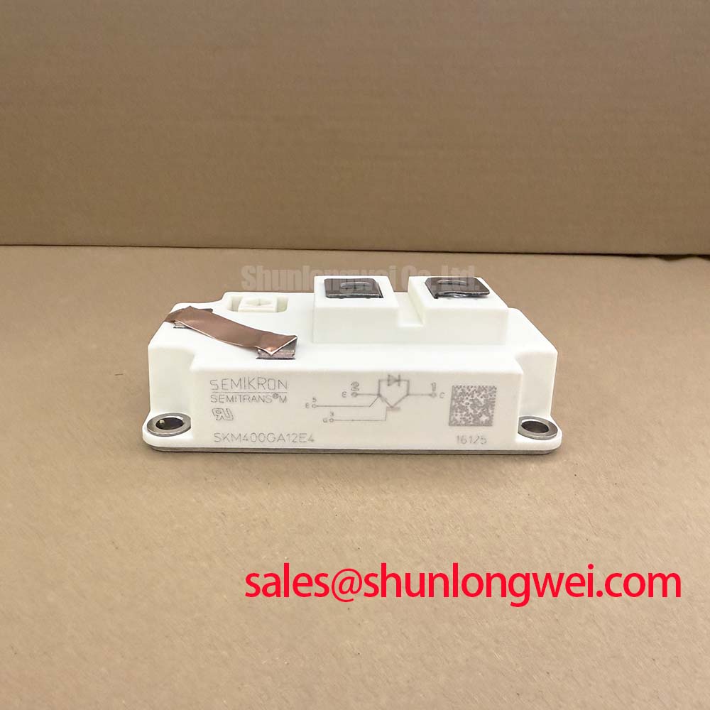
The Semikron SKM400GA12E4 is a 1200.0 V, 400.0 A IGBT module with a Semitrans package designation. These are device ratings, not unconditional operating limits for an assembled system. Its integration assessment should connect those electrical ratings with the actual terminal arrangement, cooling interface, gate-driver behavior, and protection response. The engineering guidance below is identified as Design Consideration or Engineering Recommendation; it does not add manufacturer ratings.
Measure usable thread engagement against the complete joint stack, including the conductor, washer arrangement, and screw, rather than selecting fasteners by external appearance. As a Design Consideration, the terminal joint should clamp without bottoming, interfering with adjacent features, or requiring the busbar to be pulled into position. Support the conductor independently so that its weight and assembly tolerances do not become continuous loads on the module terminals.
Inspect mating surfaces for contamination, burrs, displaced washers, and witness marks suggesting uneven contact. Where a connection has experienced repeated heating, compare its condition with adjacent joints and inspect the external conductor support. Discoloration or movement warrants investigation, but neither establishes an internal leadframe crack. A defensible diagnosis separates accessible joint resistance, external mechanical loading, and semiconductor behavior instead of assigning all symptoms to an inaccessible internal structure.
Engineering Recommendation: use the specified terminal hardware and manufacturer tightening procedure, keeping terminal-screw requirements separate from baseplate mounting requirements. Record the fastening sequence and inspect whether the busbar remains relaxed after assembly. Washer selection and preload retention belong to the approved joint design; adding washers arbitrarily can change engagement depth and electrical spacing.
For procurement and equipment-record matching, the principal specification fields are: Manufacturer: Semikron; Part Number: SKM400GA12E4; Collector-Emitter Voltage (Vces): 1200.0 V; Rated Collector Current (Ic): 400.0 A under the specified datasheet conditions; Package: Semitrans; Configuration / Topology: IGBT Power Stage. The housing and circuit description supplied for this model is SEMITRANS 4 / Single Switch. The SKM400GA12E4 product page provides the model-specific procurement reference.
SKM400GA12E4 Circuit Protection & Reliability: Thermal Time Constants and Peak Junction Temperature
Capture the overload pulse duration, repetition pattern, and case-temperature history before assessing peak junction temperature. Design Consideration: a case-temperature reading cannot follow every junction excursion during a short overload. Evaluate transient heating with the module-specific transient thermal impedance data and the actual conduction and switching loss waveform, rather than treating continuous current rating as a pulse-temperature prediction.
An Engineering Calculation can represent the junction-to-case response with a fitted multi-RC thermal network. Apply the loss history to that network and add the resulting junction-to-case temperature rise to the measured case-temperature boundary. The fit must reproduce the relevant manufacturer thermal curve over the pulse-duration range being assessed; coefficients taken from another module do not establish this model’s thermal margin. Repeated pulses require accounting for residual heating between events.
At the mounting interface, inspect heatsink flatness, surface cleanliness, and the thermal interface material application. Engineering Recommendation: follow the qualified material deposition method and mounting sequence to obtain a consistent interface without forcing the baseplate to accommodate mounting distortion. Thermal compound thickness and mounting torque should come from the applicable assembly instructions, not from a generic module value. Uneven contact can distort the thermal assessment even when coolant or heatsink temperature appears acceptable.
Coordinate desaturation monitoring with normal turn-on behavior. Design Consideration: the detector observes collector-emitter voltage during commanded conduction, but its blanking interval, filtering, propagation delay, and shutdown sequence must distinguish normal switching transients from a fault. Do not interpret normal on-state voltage as a universal desaturation threshold. Evaluate a two-stage soft turn-off strategy against fault-current decay and collector-emitter overshoot, using the device’s documented short-circuit limits and the implemented driver response.
For broader operating context, The Critical Role of IGBTs in Electric Vehicle Drivetrains discusses IGBT system functions; it is background reading, not model-specific lifetime evidence. The manufacturer’s Semikron-Danfoss SKiiP® Technology resource addresses a separate technology platform and should not be used to attribute its construction or protection features to the SKM400GA12E4.
Assembly Integrity & Layout Architecture: Auxiliary Kelvin Emitter vs Main Power Emitter for SKM400GA12E4
Trace the driver return against the module terminal drawing before connecting it to an emitter node. Design Consideration: a main load-current emitter connection and an auxiliary emitter connection serve different circuit roles where the latter is provided. Identify the actual terminal functions from the drawing; do not infer a dedicated Kelvin return from package appearance or a neighboring part number.
Keep the gate-drive outgoing and return paths closely coupled and separate their routing from the high-current commutation path. Shared emitter-path inductance can shift the voltage seen by the driver during current transitions, while collector-voltage transitions can couple through gate-collector capacitance. Assess these effects by observing gate-emitter voltage at the device-side reference with suitable probing. A waveform referenced only to a remote driver ground can conceal local emitter movement.
Engineering Recommendation: evaluate negative off-state bias, gate clamping, and driver common-mode immunity as coordinated system choices rather than automatic additions. Their settings depend on permissible gate voltage, driver capability, switching behavior, and layout. Shielding and return routing should reduce coupled noise without introducing an unintended current path through the control reference.
Pro Tip: Keep the commutation busbar arrangement compact and balanced, then verify turn-off voltage margin with a controlled double-pulse test before accepting the layout.
For replacement assessment, SEMIX604GB12T4S is a separate comparison candidate, not an established drop-in substitute. The table distinguishes known baseline fields from items requiring datasheet comparison.
| Assessment item | SKM400GA12E4 | SEMIX604GB12T4S |
|---|---|---|
| Manufacturer | Semikron | Consult Datasheet |
| Collector-emitter voltage | 1200.0 V | Consult Datasheet |
| Rated collector current | 400.0 A under the specified datasheet conditions | Consult Datasheet |
| Housing and circuit | SEMITRANS 4 / Single Switch | Consult Datasheet |
| Replacement qualification | Reference terminal, mounting, thermal, and driver requirements | Compare circuit configuration, dimensions, terminals, thermal behavior, and switching characteristics |
When evaluating a utility-scale centralized battery energy storage PCS, designers should verify converter topology, bidirectional current paths, cooling capability, and protection coordination before selecting this module. A system component review may also include MG400Q1US1, but its circuit role and drive requirements require independent assessment; it should not be assigned an upstream rectifier function from the part number alone.
Preventing Spurious Faults: Pre-Installation Junction Health Check Guidelines for SKM400GA12E4
Discharge and verify the DC link, disconnect external current paths, and identify the collector, emitter, and gate terminals before using diode-check mode. Design Consideration: the multimeter’s test voltage and current affect its reading, so record instrument type, polarity, and device temperature when comparing modules. Maintain the gate in a controlled off-state using an appropriate handling arrangement.
Check the main terminals in both polarities against the documented circuit, including the antiparallel diode path. Compare observations with a known-good device under equivalent conditions rather than imposing a universal forward-voltage pass band. An unexpected reading can arise from residual circuitry, gate charge, contact quality, or device damage; isolate these possibilities before rejecting the module. A cold diode check does not establish blocking capability at rated voltage.
Inspect gate-to-emitter and gate-to-collector behavior with a suitable low-energy method. A multimeter can reveal gross abnormal conduction, but it cannot certify gate leakage against manufacturer limits. Use the specified test conditions and controlled equipment for a quantitative leakage assessment, with protection against accidental gate overstress.
Before reconnecting the driver, inspect terminal spacing with the final busbars, washers, and insulating barriers installed. Engineering Recommendation: assess creepage and clearance for the assembled system’s working voltage, contamination environment, and applicable insulation requirements. Verify driver supply polarity, inhibit behavior, and fault reporting separately, then progress through controlled energization while recording gate-emitter and collector-emitter waveforms at the module terminals.