
Content last revised on September 10, 2026
SKM800GA126DH14 Operational Boundaries: Evaluating Dynamic Power Loss Dissipation and Multi-R Limits
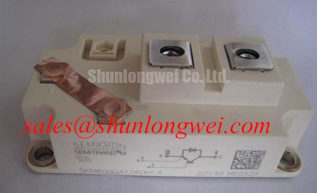
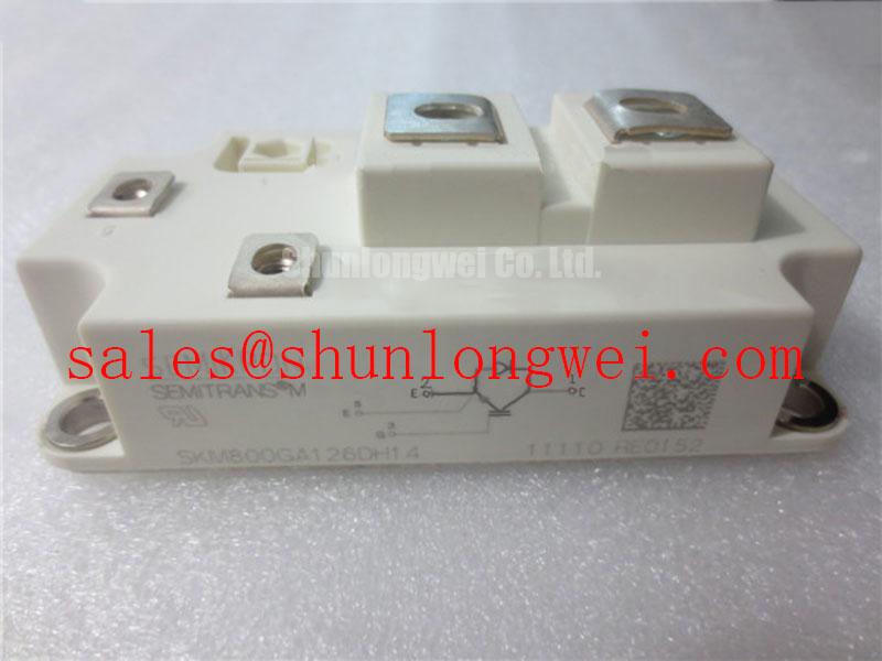
Before fitting the module, verify the converter bill of materials and nameplate boundary against SKM800GA126DH14: the specified voltage and current ratings are 1200 V and 800 A, supplied in the SEMITRANS housing. Inspect the mating heatsink for flatness, dried thermal interface material, blocked airflow, and uneven terminal contact marks before any electrical recommissioning work.
This Semikron IGBT module should be assessed as a power-switching element within its original converter topology, gate-drive arrangement, DC-link configuration, cooling path, and protection architecture. The published voltage and current ratings identify the device boundary, but system switching energy, thermal cycling, busbar inductance, and overload behavior must be verified against the original equipment documentation and measured operating conditions.
| Parameter | Official Specification |
|---|---|
| Manufacturer | Semikron |
| Part number | SKM800GA126DH14 |
| Collector-emitter voltage rating | 1200 V |
| Specified current rating | 800 A |
| Housing | SEMITRANS |
The SEMITRANS package family is part of the established industrial module ecosystem documented by Semikron-Danfoss SEMITRANS industry-standard IGBT information. Device-level integration still requires confirmation of terminal arrangement, driver connector assignment, diode topology, creepage conditions, and mechanical drawing from the original equipment documentation.
During a shutdown investigation, begin by comparing heatsink condition and cooling-path resistance with the last known stable operating state. A module carrying repetitive high-current pulses can experience junction temperature movement that is not visible from the heatsink surface alone. The temperature response has fast and slow thermal components, often represented in engineering work by a multi-RC thermal model. A numerical junction-temperature calculation requires the manufacturer thermal impedance curves, switching-loss data, actual pulse profile, case temperature, and the installed thermal interface condition. Those values should not be inferred from the 1200 V, 800 A nameplate ratings alone.
Design Consideration: treat every pulsed overload event as a combined electrical and thermal check. Capture collector current, DC-link voltage, gate waveform, case temperature trend, and fault timing together. If the waveform shows an increasing overshoot or an altered switching edge after maintenance, inspect laminated busbar joints, DC-link capacitor connections, driver-return routing, and gate-loop continuity before attributing the behavior to the IGBT module.
Clearance around the module should permit unrestricted cooling air, safe probe access, and repeatable fastening service. Do not allow harnesses or control leads to rest against high-current terminals or sharp heatsink edges. Where contamination is present, remove loose dust with an appropriate nonconductive cleaning method and examine whether moisture or conductive residue has entered the surrounding converter assembly. Condensation control is an enclosure-level responsibility and should be reviewed with the cabinet sealing, heater, ventilation, and operating-temperature strategy.
⚠️ Maintenance Note: Regularly monitor terminal-area temperature rise and verify that the cooling-air path remains clear after every scheduled cabinet cleaning.
For a utility-scale centralized battery energy storage PCS, charge and discharge duty can impose sharply different load durations. The system team should validate peak junction-temperature margin using measured mission profiles rather than assuming that a steady current condition represents the most demanding thermal case. This approach also separates a genuine cooling limitation from a control-loop issue, current-sensor offset, or abnormal circulating current.
Transient Dynamics & Electrical Design: Multi-Module Parallel Current Sharing on SKM800GA126DH14
When parallel modules are evaluated, first establish whether the converter architecture, timing references, gate drivers, current sensing, protection thresholds, and physical busbar paths were designed for parallel operation. The positive temperature coefficient associated with IGBT conduction behavior can assist static current sharing in some operating regions, but it does not guarantee balanced dynamic current during switching. Gate-loop asymmetry, unequal power-loop inductance, driver propagation variation, and differences in local DC-link connection can shift current rapidly from one module position to another.
Engineering Recommendation: keep each parallel branch electrically and physically symmetrical wherever the converter layout permits. The gate driver should source and sink the charge needed for the actual switching condition while retaining controlled switching behavior. External gate resistance selection is a bench-tuning activity, not a fixed property established by the module’s 800 A rating. Designers should assess turn-on and turn-off waveforms, collector overshoot, current sharing, and ringing on the completed power assembly.
Gate-drive isolation also deserves examination when repeated high common-mode transitions occur. Optical or digital isolators must be evaluated as part of the driver board, including their supply integrity and common-mode transient tolerance in the installed converter. A gate waveform that appears acceptable at the isolated driver output can differ at the module terminals if the return path shares inductance with the power emitter route.
In a PCS power stage, regenerative energy transfer and DC-link regulation can expose switching devices to load reversals and rapidly changing current direction. The braking chopper and braking-resistor path, where present in the system, should be checked as a separate energy-handling function. Its control behavior, resistor condition, and bus-voltage response must be reviewed at system level rather than attributed to the IGBT module alone.
For neutral comparison during repair planning, the linked FZ800R12KS4_B2 can be reviewed alongside the original module. Any substitution decision requires confirmation of electrical topology, mechanical fit, thermal behavior, terminal layout, driver compatibility, and protection coordination by the responsible system engineer.
SKM800GA126DH14 Thermal-Electrical Optimization: Auxiliary Emitter Return Trace Separation Practical Tuning
Before changing driver-board components, trace the actual gate and emitter returns from the driver output to the installed power module. Where the original module and converter design provide an auxiliary emitter or dedicated driver return, the control return should remain separate from the main high-current emitter path until the intended reference point. This reduces mutual coupling between load-current transients and the gate-control reference. The terminal design and assigned connection points must be verified from the original module documentation and equipment schematic.
Design Consideration: minimize parasitic inductance in the gate and commutation loops to suppress turn-off overshoot and unwanted oscillation, then verify peak voltage and gate behavior against the DC-link voltage during switching tests. A long control lead, a looped return wire, or a driver ground bonded at an unsuitable power point can create apparent gate instability even when the driver supply and controller logic are functioning normally.
Use an oscilloscope with a measurement method suitable for high-energy converter work to compare gate-emitter behavior across equivalent module positions. If ringing is found, inspect driver connector retention, local decoupling condition, grounding continuity, terminal cleanliness, and routing symmetry. Avoid changing several parameters at once; a staged measurement record makes it possible to distinguish coupling effects from control-command changes.
The Evolution of Negative Off-Bias Gate Drive Circuits provides useful technical context for assessing off-state gate control. Whether a particular driver uses negative off-bias, active clamping, or another protection method depends on the existing converter design. The system integrator should retain the original validated driver strategy unless a complete electrical review supports modification.
In systems containing related front-end or supply-stage power devices, the SKM100GB063D may be relevant for topology review. It should be considered according to its own ratings and connection requirements, rather than treated as electrically interchangeable with this 1200 V, 800 A module.
SKM800GA126DH14 Thermal-Electrical Optimization: Managing High-C-Rate Battery Cycling Swing Practical Tuning
For utility-scale centralized battery energy storage PCS equipment, assess the SKM800GA126DH14 within the complete power path between battery racks, DC link, and AC-side conversion stage; where the system is designed for four-quadrant operation, include that operating range in the assessment. Heavy charging and discharging cycles can repeatedly alter current direction, switching duty, and thermal loading. The maintenance task is to identify whether the converter is seeing expected operational cycling or whether a control, cooling, sensor, or interconnect issue is increasing thermal swing beyond the intended operating profile.
Start with synchronized records from the battery management system, PCS controller, DC-link measurement, coolant or airflow monitoring, and converter fault log. Compare these records with module case-temperature trends and switching-event captures where safely available. A recurring temperature excursion may indicate restricted cooling, inconsistent thermal contact, an abnormal current command, or unequal sharing between power paths. It should be investigated through measured evidence rather than a single-cause assumption.
During planned service, inspect heatsink fins, fan performance, thermal interface aging, terminal fastening condition, and signs of vibration at power and control connections. Reapply thermal interface material only according to the original mechanical process and relevant product documentation. The official Semikron-Danfoss power electronics and modules hub is an appropriate manufacturer reference point for broader module-family documentation.
Where a PCS has undergone firmware changes, altered battery rack configuration, or revised dispatch strategy, engineers should revalidate switching stress and cooling capacity under the present duty cycle. The module’s official 1200 V and 800 A ratings remain essential identification data, while actual reliability depends on the verified interaction of electrical transients, protection response, mounting condition, and thermal management across the converter.