
Content last revised on October 4, 2026
SKMD150F12 Bench Checks Before Energizing the Circuit
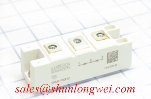
With the DC link discharged and the module isolated from the circuit, compare the cold terminal readings of the SKMD150F12 against the equipment schematic before energizing the circuit. This Semikron module is listed with a 117.0 A rated current and a Semitrans package (Official Specification). Its supplied voltage description, “Standard Industrial Rating,” does not state a numerical voltage limit; obtain the exact device datasheet before approving a DC-link voltage or insulation test.
Start incoming inspection with the terminal drawing, not an assumed pin arrangement. Identify each terminal from documentation for the exact SKMD150F12 version, then record cold resistance and diode-mode readings in both probe directions. A diode-mode result is useful for comparing like terminals and a known-good unit, but it does not establish the module’s current capability or prove that every internal junction is sound. Readings taken while the module remains connected to a busbar, driver board or snubber can include parallel circuit paths.
💡 Bench Tip: Discharge and verify the DC link before touching module terminals, and protect nearby gate-driver connections against electrostatic discharge during cold measurements.
For a driver replacement in the host equipment, treat optocoupler and digital coreless-transformer isolation as properties of the driver design, not specifications of the SKMD150F12. As a Design Consideration, compare the driver’s documented isolation rating and common-mode transient immunity with the equipment’s insulation requirements and measured switching environment. Neither an isolation threshold nor a transient-immunity figure can be assigned to this module from its stated 117.0 A rating.
On an instrumented bench, observe the equipment’s gate signals relative to their documented returns during switching. If an unexpected pulse appears, compare it with the driver input, supply rails and switch-node transition before attributing it to a particular component. Maintain the clearances required by the equipment design and applicable insulation scheme; the system designer must verify those distances against its operating voltage, environment and governing standard. Semikron-Danfoss provides a power electronics and modules information hub for locating manufacturer documentation, but the exact part documentation remains the basis for pin and limit checks.
SKMD150F12 Switching Stress and Overvoltage Checks
When a repaired converter trips on DC-link overvoltage, capture the bus voltage and module terminal waveforms at the same operating event. Separate a sustained rise in bus voltage from a brief switching overshoot: they point to different checks. A braking IGBT and resistor, where the equipment uses them, belong to the system’s energy-management circuit. Their ratings must be assessed from the measured operating cycle, stored or returned energy, resistor thermal limits and control thresholds; the SKMD150F12 current figure alone cannot size them.
As a Design Consideration, inspect the commutation path and any fitted snubber if overshoot coincides with a switching edge. Parasitic inductance and diode reverse recovery can affect the observed waveform, but the relevant diode topology and recovery characteristics must first be confirmed from the exact module documentation. Compare measurements at equivalent operating conditions before changing the equipment’s gate network or snubber. The equipment engineer should verify peak voltage against the module’s documented limit once that numerical limit is available.
Changes that soften a switching edge can also change loss and temperature. Measure the resulting voltage, current and temperature behavior rather than treating a quieter waveform as proof of adequate margin. Radiated-emissions performance is an equipment-level matter; a module or snubber adjustment does not establish EMC compliance. For context on application-level operating conditions, the Industrial Applications resource discusses power-module use across industrial systems without replacing the SKMD150F12 datasheet or equipment test results.
SKMD150F12 System Gate-Drive and Thermal-Electrical Evaluation
If a controlled switch in the converter shows an unintended gate excursion, measure its gate-to-emitter voltage at its documented control terminals while monitoring the switching node. A fast voltage transition can couple into a gate circuit; a shared return path or driver behavior may contribute as well. These are diagnostic possibilities, not a diagnosis from a single oscilloscope trace. Compare the suspect leg with a working leg under matched conditions and check probe connections before changing components.
An active Miller clamp, separate turn-on and turn-off paths, or negative off-state bias may be evaluated as Design Considerations where the existing driver supports them. None is an SKMD150F12 factory requirement established by the supplied specifications. Select and validate gate-drive behavior using the controlled switch’s limits, driver documentation, measured gate excursions and switching-loss results. Avoid assigning a bias voltage or gate resistance from the SKMD150F12 name or package alone.
For thermal assessment, confirm that the Semitrans package fits the equipment’s mounting arrangement, then inspect the contact surfaces and follow the applicable manufacturer mounting instructions. Record temperature at repeatable operating points while checking that electrical stress remains within documented limits. Semikron-Danfoss describes single-sided sintering technology as a packaging technology; that information does not establish that this particular SKMD150F12 contains a sintered interface or specify its lifetime.
For a cross-model purchasing review, SKM75GAL063D can be placed on a comparison list, but it should not be treated as a direct replacement on the strength of a model name. Verify device type, circuit topology, terminal assignment, voltage and current limits, mechanical fit, drive requirements and thermal characteristics against both exact datasheets and the host equipment.
SKMD150F12 and Equipment Return-Path Checks for Spurious Faults
Trace the equipment’s gate-driver return from its board connector to the controlled switch’s documented return terminal, rather than assuming the SKMD150F12 has a gate connection. If the controlled switch and equipment wiring provide a dedicated sensing return, keep its route distinct from the high-current power path as a Design Consideration; the purpose is to reduce shared-path voltage disturbance during switching. The final routing and spacing still require verification in the equipment layout.
During fault investigation, capture the controlled switch’s gate signal at its device connection as well as at the driver output. A difference between those observations may indicate wiring impedance, return-path coupling or a measurement-reference problem. Check connector seating and continuity with power removed, then repeat the waveform comparison under controlled conditions. If the fault coincides with a current transition, inspect the physical power-loop and control-return paths before altering protection settings.
For a proposed industrial inverter welder or medium-frequency induction-heating power-supply repair, confirm the original module designation and terminal map first. Use the 117.0 A rated current and Semitrans package as initial identification points, then resolve the missing numerical voltage rating and all switching, insulation and mounting limits from the exact manufacturer documentation before energizing the assembly.