



Content last revised on September 18, 2026
SKMT 132/04E Specifications and Initial Checks
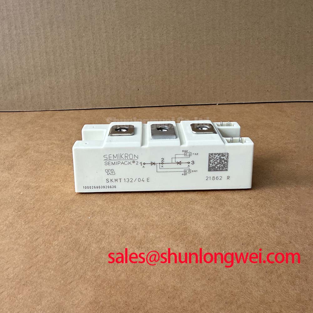
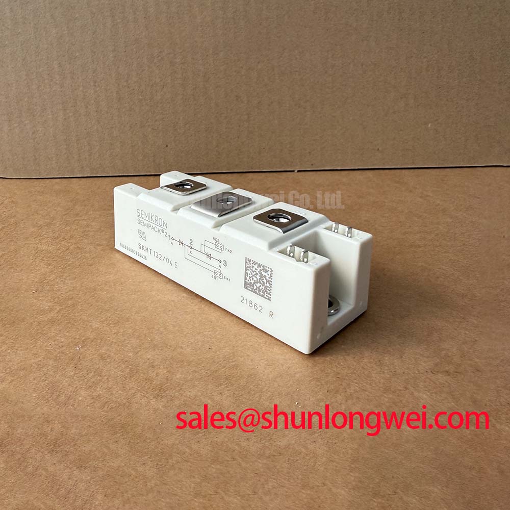
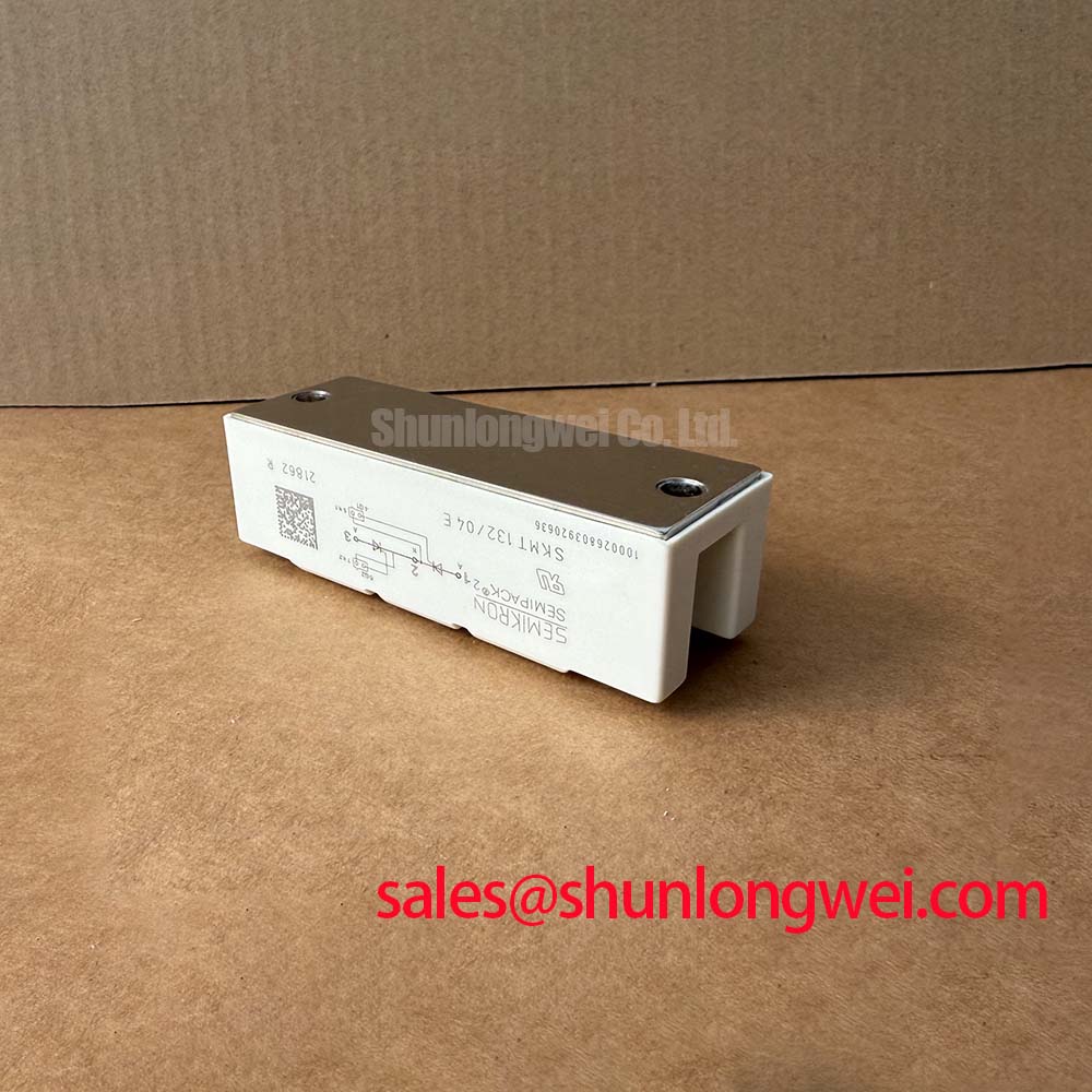
With the equipment isolated and discharged, verify the terminal identification against the original schematic before applying any meter test to the SKMT 132/04E. This is a Semikron thyristor module, so its conduction and control behavior must be assessed as a phase controlled power device rather than as an IGBT switching module. The official device ratings are 400 V VRRM and VDRM, 130 A IT(AV) at TC = 85°C, and 4700 A ITSM at 10 ms and 25°C.
| Official Specification | Rated Value | Engineering Relevance |
|---|---|---|
| Repetitive peak reverse and off state voltage | 400 V | VRRM and VDRM rating for applicable line commutated power stages |
| Average on state current | 130 A at TC = 85°C | Rated average on-state current under the specified case-temperature condition |
| Surge current | 4700 A, 10 ms, 25°C | ITSM capability for non repetitive fault or inrush events |
| Maximum on state voltage | 1.55 V | VTM conduction loss reference |
| Junction to case thermal resistance | 0.18 °C/W | Rth(j c) thermal path from semiconductor junction to module baseplate |
| Isolation test voltage | 3000 V AC | Specified Viso isolation test voltage |
The SKMT 132/04E can be evaluated for controlled rectifier and AC power regulation assemblies used around 220 V or 240 V AC line systems. In commercial string inverter and micro grid energy storage equipment, a system engineer may encounter this device in an upstream line controlled charging, precharge, auxiliary conversion, or service replacement assembly, subject to verification of the original circuit topology and terminal arrangement.
Benchtop Waveform Tuning: Overcurrent Protection Boundaries for SKMT 132/04E
A thyristor module does not use the IGBT short circuit safe operating area concept, gate desaturation detection, or active soft turn off sequence. Once triggered into conduction, a conventional thyristor remains latched until the circuit current falls below its holding condition through natural or forced commutation. Any protection scheme must therefore be designed around the actual commutation method and the available upstream interruption path.
For bench commissioning, first confirm that the controller is issuing the intended firing pulses at the correct phase reference and that the power circuit can commutate the device as expected. A missing, delayed, or incorrectly referenced firing pulse can cause asymmetric conduction in a controlled rectifier. An unexpected current waveform may also arise from load imbalance, incorrect line synchronization, an open phase, insufficient commutation voltage, or a damaged snubber network. It should not be attributed to the module without measured evidence.
The official 4700 A ITSM value is a non repetitive surge rating measured under the stated condition of 10 ms at 25°C. It is not a permitted continuous fault current or a substitute for coordinated semiconductor protection. Design Consideration: evaluate the upstream protective device, load fault behavior, cable impedance, and interruption timing as a complete assembly. The protection response must be validated against the actual prospective fault current and thermal state of the installed equipment.
Phase angle control affects input current shape. Delaying the firing angle changes the portion of each AC cycle delivered to the load, which can increase distortion and reactive demand in the associated supply system. Where harmonic performance matters, designers should validate line current with suitable power analysis instrumentation and confirm that filtering, control timing, and source impedance are appropriate for the equipment installation.
💡 Pro Tip: Keep the high current busbar route compact and mechanically symmetric around the controlled current path, then verify switching and commutation transients with measurements on the finished assembly.
Field Diagnostics and Commissioning: Altitude, Neutron Exposure, and 400 V Topology Boundaries
Before energizing a replacement assembly, inspect the module mounting surface, busbar contact faces, fasteners, insulation hardware, and wiring clearances. Confirm the terminal positions from the equipment drawing or the module documentation rather than inferring them from busbar shape. A cold resistance measurement can help identify an unintended short in the surrounding power circuit, but it cannot by itself establish correct thyristor triggering or commutation behavior.
Atmospheric neutron exposure and single event burnout calculations require device specific qualification data, operating voltage distribution, environmental profile, and a defined failure rate model. No FIT rate, altitude derating value, or single event burnout probability should be assigned to the SKMT 132/04E without a relevant manufacturer source or an application qualified reliability study. For sites above 2000 m, Design Consideration: the system integrator should review insulation coordination, enclosure contamination level, cooling capability, and local regulatory requirements because the complete assembly, rather than the module alone, determines installation suitability.
The 400 V repetitive blocking rating defines the semiconductor voltage boundary, not the complete DC bus design margin. Measure line transients and commutation overshoot at the module terminals under representative load conditions. Suppression components, cable routing, transformer leakage inductance, and supply disturbances can all influence the observed peak voltage. Engineers should verify that measured stress remains within the applicable limits for the device and the assembled equipment.
Vibration resistance also depends on the busbar structure, fastening method, enclosure stiffness, and cable support. Use the original equipment fastening practice where available, and check for movement that could alter electrical contact pressure or compromise creepage distances. For a broader manufacturer context on power semiconductor product families, consult the Semikron Danfoss Power Electronics and Modules official hub.
SKMT 132/04E Thermal Electrical Optimization: Conduction Loss and Current Distribution
The relevant forward conduction specification for the SKMT 132/04E is VTM maximum 1.55 V. Conduction loss rises with current and operating temperature, so heatsink condition, thermal interface quality, airflow, and nearby heat sources must be reviewed during service work. The official Rth(j c) of 0.18 °C/W describes the junction to case portion of the thermal path only; it does not include the case to heatsink interface or the heatsink to ambient path.
When checking an existing unit, look for uneven thermal compound coverage, contamination between the module and heatsink, distortion of the mounting face, and signs that busbars are applying mechanical stress to the package. These conditions can raise junction temperature even when the external heatsink appears adequate. The mounting torque and thermal interface process should follow the applicable module documentation and equipment manufacturer procedure rather than a generic value.
Parallel current sharing should not be assumed from a single forward voltage measurement. Static sharing can be influenced by device temperature, connection resistance, trigger timing, heatsink gradients, and the current waveform. Dynamic imbalance in controlled AC circuits can arise when firing references or gate pulse delivery differ between parallel paths. Engineering Recommendation: use matched physical routing, comparable contact resistance, and synchronized firing circuitry, then validate individual branch currents under the real operating waveform.
Where an equipment repair review also involves a transistor based inverter stage, the SKM75GB07E3 is a separate IGBT module reference for topology comparison. It should not be treated as a direct replacement for this thyristor module because switching device behavior, drive requirements, commutation method, package arrangement, and circuit function must be verified at system level.
Long motor cable reflection, inverter dead time, and IGBT gate loop behavior belong to voltage source inverter output stages, not to the operating mechanism of the SKMT 132/04E. If a commercial energy system contains both a line controlled front end and an IGBT inverter section, troubleshoot each power stage according to its own device technology and measured waveforms.
Preventing Spurious Faults: Isolation Barrier Integrity Guidelines for SKMT 132/04E
The specified isolation test voltage of the SKMT 132/04E is 3000 V AC. This value should be treated as a module specification and not as proof that the completed equipment provides reinforced insulation, a particular common mode transient immunity level, or independent compliance with system EMC standards. Those outcomes depend on the enclosure, spacing, insulation system, PCB design, grounding arrangement, control interface, and applicable equipment certification program.
Before commissioning, inspect the module isolation area for conductive debris, moisture paths, damaged barriers, improperly positioned busbars, and hardware that could reduce clearance. The system integrator should confirm creepage and clearance distances according to the equipment insulation coordination requirements and the intended pollution environment. If an insulation test is part of the repair procedure, use the voltage, duration, connection points, and acceptance criteria specified by the equipment documentation.
Spurious firing or unexplained phase conduction requires measurement of the trigger circuit and line reference rather than an assumption about isolation failure. Review the trigger source, pulse transformer or interface circuit where fitted, gate return routing, noise coupling from adjacent conductors, and supply synchronization. Oscilloscope measurements should be referenced safely and compared with a known good phase path whenever possible.
For engineers assessing modern industrial drive technologies alongside legacy controlled rectifier hardware, Unlocking Efficiency in Industrial Drives provides related IGBT technology context. Semikron Danfoss product architecture for integrated power module families can also be reviewed through its MiniSKiiP power modules resource, while maintaining the necessary distinction between integrated IGBT assemblies and the SKMT 132/04E thyristor module.