




Content last revised on September 25, 2026
Field Diagnostics & Commissioning: Sinusoidal 10 ms Half-Cycle Surge Current in SKR26/12 Topologies
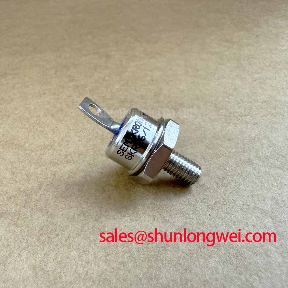
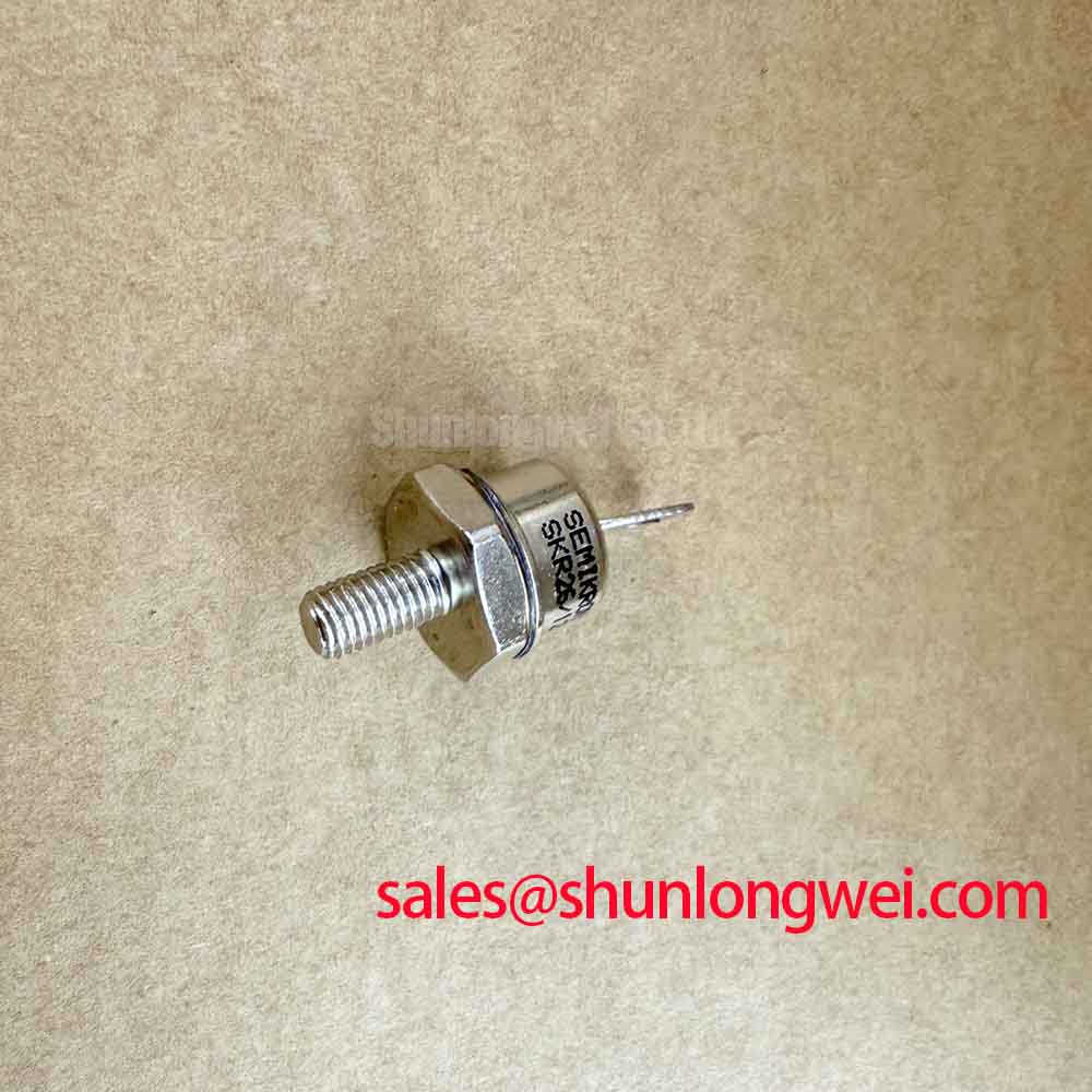
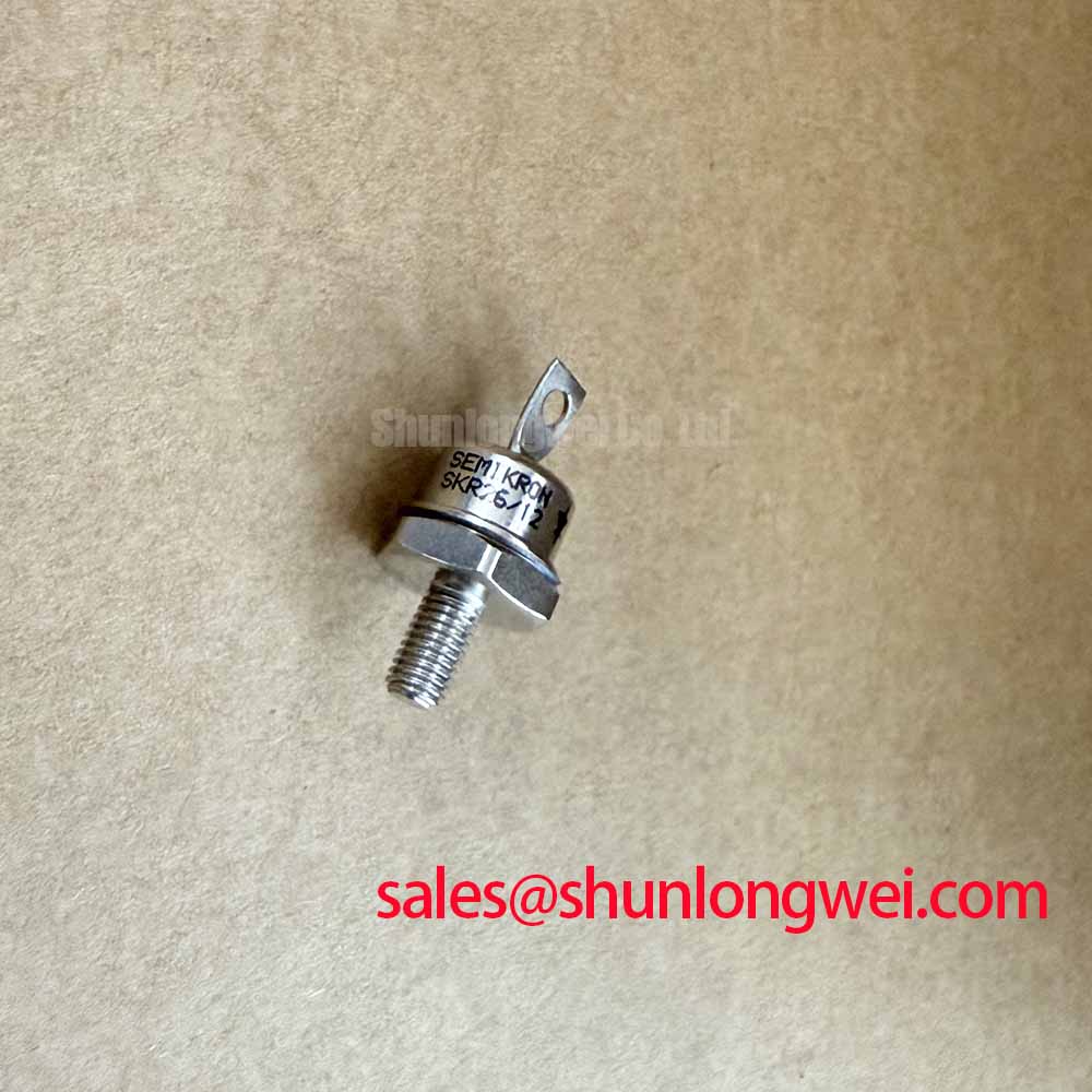
The Semikron SKR26/12 is a stud-mounted fast recovery power diode rated at 1200 V VRRM and 25 A IFAV at Tc = 100°C as an Official Datasheet Specification. Its 375 A IFSM rating applies to a sinusoidal 10 ms half-cycle surge condition. This figure is useful when reviewing a failed rectifier, freewheel path, or commutation circuit after an inrush event, but it should not be treated as a continuous overload allowance.
During commissioning, confirm that the original topology applies reverse voltage as intended during commutation and that the measured current path agrees with the schematic. A diode-test reading can identify an obvious short or open condition, yet it cannot verify recovery behavior under working voltage and current. If a soft starter has repeated fuse operation, check the phase wiring, contactor transition sequence, snubber condition, and heatsink contact before assigning the event to the diode itself.
| Parameter | Official Datasheet Specification | Practical Verification Use |
|---|---|---|
| Repetitive peak reverse voltage | 1200 V | Confirm suitability against the measured system blocking requirement. |
| Mean forward current | 25 A at Tc = 100°C | Review against actual heatsink temperature and continuous current duty. |
| Surge forward current | 375 A, 10 ms half sine wave | Review transient exposure and fuse coordination records. |
| Recovery type | Fast Recovery | Relevant where reverse recovery affects switching stress and noise. |
| Package | Threaded stud | Supports direct chassis or heatsink mounting when hardware is correctly secured. |
Fuse coordination is a Design Consideration. The semiconductor fuse time-current curve and pre-arcing I²t data should be compared with the equipment fault study and the diode surge limitation stated by the manufacturer. Do not infer a Type 2 coordination result from the 375 A surge rating alone. Where a higher-current module is being reviewed elsewhere in the same cabinet, SKT340/18E can serve as a separate reference point for topology and mounting comparison, subject to full electrical and mechanical verification.
Field Alert: Tighten the stud connection according to the applicable Semikron hardware documentation and use a clean, evenly prepared heatsink interface before energizing the circuit.
Preventing Spurious Faults: Surge Energy Dissipation and Clamping Volt Guidelines for SKR26/12
For AC input sections exposed to surge events assessed under IEC 61000-4-5, protection components ahead of the power semiconductor should be evaluated as a system. MOVs, RC snubbers, line impedance, contactor behavior, and cable routing each influence the transient presented to the 1200 V blocking path. The system engineer should verify clamping performance at the actual installation point rather than assuming that a nominal MOV marking represents the voltage seen at the diode terminals.
Fast recovery behavior can reduce reverse-recovery-related switching losses in suitable circuits, but it does not eliminate voltage overshoot caused by wiring inductance. A Design Consideration is to keep the high-current loop compact, particularly between the diode, suppression network, and associated controlled devices, then verify peak terminal voltage with properly referenced test instrumentation. ROHM’s high-speed fast recovery diode guidance provides useful background on the relationship between recovery characteristics and switching applications.
Where a cabinet includes an energy-buffering stage, the upstream charging and discharge paths should also be checked for unintended surge circulation. A supercapacitor energy buffer is a system-level option in some industrial power architectures, not an attribute of the SKR26/12. Its connection and protection requirements must be established from the equipment design documentation.
SKR26/12 Thermal-Electrical Optimization: Type 2 Coordination and Sub-Cycle Dead-Short Practical Tuning
A dead-short investigation should begin with physical evidence: inspect fuse links, bus joints, semiconductor mounting pressure, and evidence of arc tracking around terminals. The 25 A mean forward-current specification is stated at Tc = 100°C; it does not define performance at an unknown heatsink temperature or under repetitive fault duty. Check the original thermal path, airflow condition, and interface flatness before returning a replacement diode to service.
Type 2 coordination is a system claim that depends on the selected protective device, prospective short-circuit current, controller response, contactor behavior, and tested assembly. Engineering Recommendation: obtain the fuse manufacturer’s I²t coordination information and compare it with the complete protection path. The purpose is to establish whether the fuse clears the fault before semiconductor stress exceeds the applicable device limitation, not to claim zero damage from a single component rating.
For a related rectifier or supply-stage review, SKT240/18E is a neutral linked reference for engineers comparing devices within broader power-conversion assemblies. Electrical ratings, terminal arrangement, cooling conditions, and original circuit function must be independently confirmed before any substitution decision.
Benchtop Waveform Tuning: Mitigating Stress via Phase-Controlled Rectification and Firing Angle Checks on SKR26/12
The SKR26/12 is a fast recovery diode, so it has no gate firing angle of its own. In phase-controlled rectification, the firing angle belongs to the upstream thyristor or controlled switching element, while this diode can form part of the commutation, freewheel, or rectification path defined by the circuit. When evaluating firing angles from zero through late-phase conduction, observe line current shape, DC output behavior, reverse voltage across the diode, and the timing relationship between control pulses and current transfer.
Late firing can alter power factor and increase harmonic current demand, but the resulting impact depends on source impedance, motor load, control method, and installed suppression hardware. Designers should capture waveforms under controlled conditions and verify that measured reverse-voltage peaks remain within the 1200 V VRRM official rating. If switching stress or ringing is under review in a three-phase conversion stage, The 1200 V CoolSiC™ MOSFET Advantage in Three offers related technical context on 1200 V power-conversion considerations.