




Content last revised on September 21, 2026
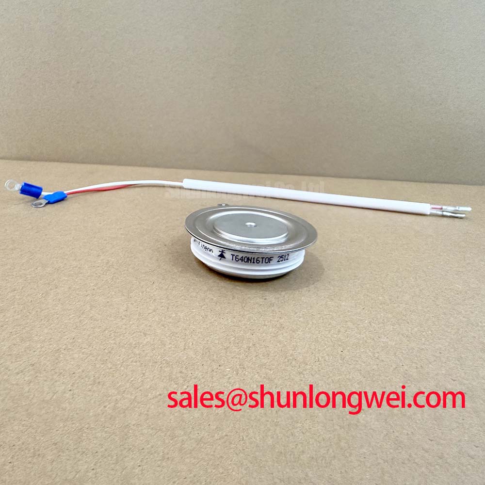
With the soft starter isolated and discharged, first inspect the clamping faces, terminal interfaces, and surrounding bypass contactor path before assessing the T640N16TOF. Confirm that the existing assembly matches the required press-pack arrangement and that no conductor, busbar, or cooling plate deformation can prevent even contact pressure. This Infineon thyristor and diode module is specified with a 1600 V repetitive peak reverse voltage, 644 A average on-state current at case temperature of 85 degrees C, and 9400 A surge on-state current for 10 ms at 125 degrees C.
For a high-voltage three-phase motor solid-state soft starter, these figures establish the electrical boundary for the replacement assessment, not an automatic approval of the complete starter. The service engineer should compare phase voltage, original device position, firing circuit arrangement, current transformer feedback, semiconductor fuse documentation, and bypass contactor operation with the equipment schematic. A soft starter fault can originate in the control board, gate pulse transformer, phase sensing chain, snubber assembly, or mechanical clamping system; static checks of the removed power device should be interpreted alongside the known circuit path.
Assembly Integrity & Layout Architecture: Managing Bypass Contactor Thermal Duty Cycle for T640N16TOF
In a phase-angle-controlled motor starter, the thyristor path carries the controlled current while the motor accelerates, then the bypass contactor normally assumes the steady running current. The practical purpose of this arrangement is to restrict locked-rotor current and reduce torque shock during starting. Depending on the motor and starter control strategy, engineers often target a controlled start current below the direct-on-line locked-rotor condition, which can commonly be several times rated motor current. The final current limit, ramp profile, and bypass transfer point remain system-determined and require validation against the motor load and starter control documentation.
The 644 A I_TAVM rating at T_C = 85 degrees C is an Official Specification and must be read with its stated case-temperature condition. It does not replace a thermal calculation for the actual cooling plates, airflow, start frequency, overload profile, or bypass-contactor duty cycle. The published 0.039 K/W junction-to-case thermal resistance with double-sided cooling identifies the intended thermal path condition. A field replacement should therefore verify that both cooling faces are clean, flat, and correctly aligned with the original hardware before the assembly is energized.
The official mounting-force requirement is 6 to 12 kN. This is a controlled clamping-force requirement, not a published bolt-torque specification. The installer should follow the equipment manufacturer’s clamping arrangement, bolt sequence, and force-setting procedure, because applied bolt torque is influenced by fastener size, lubrication, washer arrangement, and fixture geometry. Field Alert: Do not substitute a guessed bolt torque for the specified 6 to 12 kN clamping-force requirement; unequal pressure can compromise both electrical contact and heat transfer.
Semiconductor fuse coordination must also be checked against the original starter’s fuse documentation. No fuse I2t value is stated in the supplied product specifications, so a replacement decision should not assign one. Confirm the original fuse type, its coordinated protection data, conductor routing, and the starter manufacturer’s permissible fault-clearing arrangement. The device’s 9400 A, 10 ms, 125 degrees C I_TSM value is an Official Specification for surge on-state current, but it is not a substitute for system fault protection coordination.
Assembly Integrity & Layout Architecture: Evaluating Reverse-Recovery Behavior for T640N16TOF
Before treating a commutation issue as a device failure, compare the incoming phase waveforms, firing order, and snubber connections with a known-good phase where available. The supplied official information identifies the T640N16TOF by reverse-voltage, average-current, surge-current, rate-of-rise, thermal-resistance, and mounting-force specifications. It does not provide reverse-recovery peak current, reverse-recovery time, recovery charge, or softness data. Those values must not be inferred from the module designation or borrowed from another device family.
In a phase-controlled AC starter, commutation behavior depends on the source impedance, motor winding condition, firing angle, line waveform, connected suppression components, and the corresponding diode and thyristor paths. A distorted waveform or unexpected recovery transient may indicate a problem in the surrounding power circuit, but an oscilloscope measurement referenced to an approved test arrangement is needed before assigning a root cause. Design Consideration: maintain the original low-inductance busbar geometry and intended return paths to limit transient voltage generated during current transfer, then verify peak device stress during controlled switching tests.
Carrier recombination is relevant to recovery behavior in power semiconductor junctions, but it should not be used to claim undocumented internal construction or switching performance for this model. For background on the physical mechanism, see Carrier Lifetime and Recombination in Power Semiconductor P-N Junctions. The appropriate service action is to use the original manufacturer documentation and measured waveforms to determine whether the recovery behavior remains within the starter’s design envelope.
When evaluating related devices within a common power-control architecture, the TT570N16 can be reviewed as a separate system-topology component. Its electrical ratings, package interface, control function, and thermal requirements must be checked independently. A shared nominal voltage class alone does not establish interchangeability in a soft-starter phase leg.
Transient Dynamics & Electrical Design: RC Snubber Network Optimization for T640N16TOF
Inspect the original RC snubber components before reconnecting a replacement module. Look for open resistors, cracked capacitors, carbon tracking, loose busbar joints, damaged gate-pulse transformer leads, and incorrect phase-to-phase wiring. These observations do not prove the source of a transient event, but they identify conditions that can change the voltage distribution across a controlled AC power stage.
The T640N16TOF is specified for a critical rate of rise of on-state current of 150 A/microsecond. This Official Specification is central when reviewing the interaction between the firing circuit, source impedance, motor current, and reactor arrangement. The system designer should minimize parasitic loop inductance to suppress inductive overshoot while confirming, through switching measurements, that the observed current rise remains compatible with the device specification and the original control architecture.
RC snubber capacitance and resistance cannot be safely prescribed from the supplied module data alone. Their required values depend on measured ringing frequency, circuit inductance, supply characteristics, device position, and the thermal duty imposed on the resistor. A saturable reactor, where present in the original equipment, likewise needs evaluation against the starter schematic and measured phase current. Replacing components with arbitrary values can alter firing stability, device dissipation, and line disturbance.
For thermal-package context, Semikron Sintering Technology discusses power-semiconductor interconnection approaches. It is background material only and does not define the internal construction, mounting method, or thermal rating of the T640N16TOF. For this part, the relevant Official Specification remains the stated 0.039 K/W junction-to-case value under double-sided cooling and the required 6 to 12 kN mounting force.
For teams assessing phase-control topology behavior during repair verification, Resonant Topologies in Home Appliances provides a separate reference on topology-level switching considerations. Its content should not be treated as a configuration prescription for a three-phase motor soft starter.
Preventing Spurious Faults: Power-Factor Degradation and Harmonic-Mitigation Guidelines for T640N16TOF
At reduced conduction angle, a phase-angle soft starter alters the motor terminal waveform and can increase reactive demand and harmonic content during the starting interval. As firing angle changes from near full conduction toward delayed conduction, the current waveform, motor torque, line power factor, and acceleration time are all affected. The actual transfer characteristic is determined by the motor, supply stiffness, load inertia, firing algorithm, and installed bypass-control logic. It should be measured and reviewed as a system behavior rather than attributed to the T640N16TOF alone.
For urgent maintenance work, verify that all three phases receive the intended firing pulses, that phase rotation and current-feedback wiring agree with the controller configuration, and that the bypass contactor closes only under the original control conditions. A missing or delayed firing pulse can create an asymmetric current pattern that may trigger protection functions or produce abnormal heating. Conversely, a controller protection indication may reflect sensing, synchronization, or contactor feedback issues rather than a failed power module.
The 1600 V V_RRM rating provides the official repetitive reverse-voltage limit for the module. Designers should verify measured phase-to-phase and transient voltage conditions against this limit during commissioning, particularly where line disturbances, long conductors, or changed suppression hardware are present. Do not infer system EMC compliance, insulation certification, altitude capability, or operating lifetime from this device rating alone; those requirements belong to the complete starter and its documented installation conditions.
If the original T640N16TOF cannot be retained in the repair plan, TD210N12 is a separate component that can be considered for a documented engineering comparison. Its voltage rating, current capability, mechanical interface, cooling arrangement, surge behavior, and triggering requirements must be compared with the failed position and the original equipment design before any substitution is approved.