Content last revised on September 16, 2026
| Official Specification | Value | Engineering Significance |
|---|---|---|
| Repetitive peak voltage, VDRM/VRRM | 1600 V | Establishes the repetitive blocking-voltage class for the power stage |
| Mean on-state current, ITAVM | 240 A at Tc = 85°C | Defines the stated continuous current capability under the specified case condition |
| Surge on-state current, ITSM | 7500 A at 10 ms and 25°C | Supports short-duration fault and inrush coordination analysis |
| I2t value | 281,000 A2s | Provides a reference for semiconductor fuse coordination and short-circuit protection analysis |
| Junction-to-case thermal resistance, RthJC | 0.124 K/W | Used with measured thermal conditions when evaluating heatsink performance |
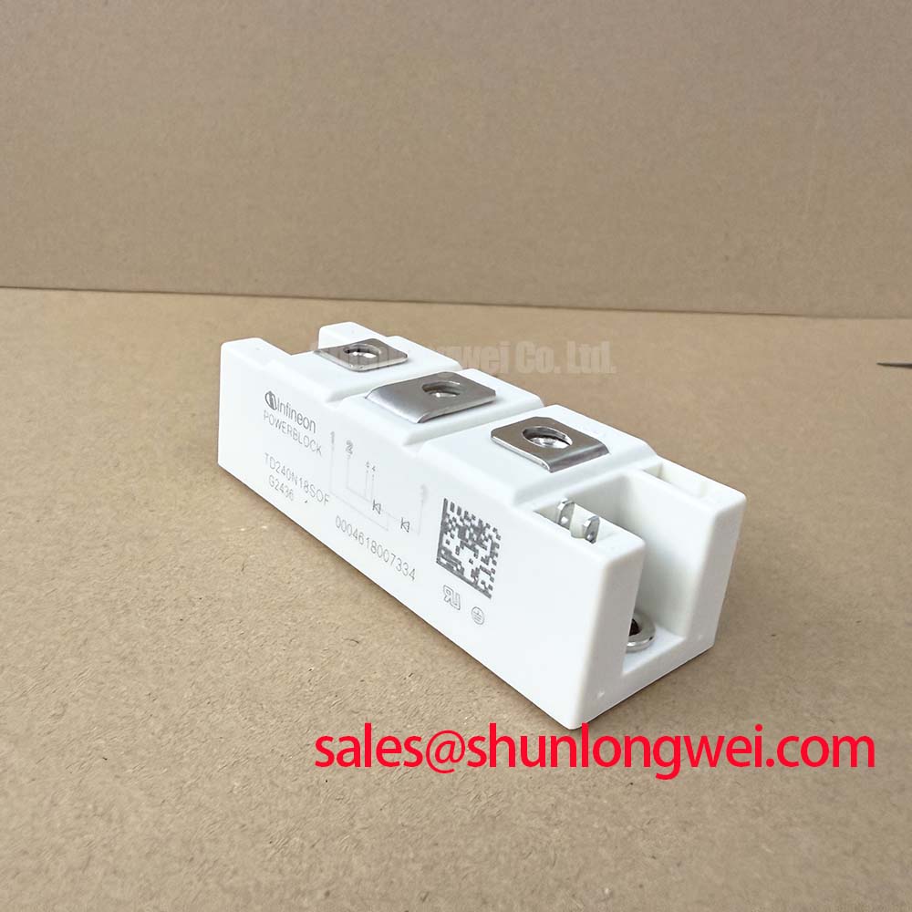
TD240N16SOF Circuit Protection and Reliability: Calibrating Thermal Interface Material Spreading
For a high-current installation, clean the heatsink and module baseplate, check flatness, and apply the thermal interface material as a continuous, controlled layer. The objective is uniform contact pressure across the copper baseplate without bending the module body. The official RthJC of 0.124 K/W is a junction-to-case specification; it does not replace system-level verification of heatsink temperature, airflow, coolant condition, or interface quality.
Use the stated I2t value of 281,000 A2s when reviewing semiconductor fuse coordination. The selected fuse and upstream protection scheme must be checked against the actual fault waveform, prospective current, clearing time, and wiring impedance. A fuse table or protection curve from the relevant design documentation is required before treating coordination as validated. Terminal hardware should be tightened according to the manufacturer’s mechanical instructions and the original assembly drawing, since the correct value depends on the terminal configuration and fastening arrangement.
Field Alert: Never loosen or connect power terminals while the DC link or AC supply can remain energized.
Assembly Integrity and Layout Architecture: Implementing AC-to-DC Transfer Characteristics
In a controlled rectifier or phase-controlled heating supply, the firing angle changes the average power delivered to the load while also affecting displacement power factor and reactive demand. The TD240N16SOF voltage class should be checked against the complete line-to-line waveform, commutation transients, and the selected protection network rather than the nominal supply alone. Designers should verify the actual gate timing, synchronization circuit, and load-current waveform with an oscilloscope during commissioning.
An MOV network may be evaluated as part of the system overvoltage strategy, but its clamping behavior, energy rating, fuse coordination, and repetitive duty remain system-design responsibilities. Gate-drive isolation also requires review of common-mode transient behavior. An optocoupler or digital isolator should be selected and tested for the switching environment, with the PCB return paths and isolation barriers arranged to limit unwanted transient coupling.
For a broader comparison of power-device voltage, current, thermal, and protection criteria, engineers can consult the Power Semiconductor Selection Guide. The TD210N12 may also be reviewed as a separate device option, but its electrical suitability must be established from its own official documentation rather than assumed from package or current similarities.
TD240N16SOF Operational Boundaries: Evaluating Sinusoidal 10 ms Half-Cycle Surge Current Limits
The official ITSM rating is 7500 A for a 10 ms half-cycle at 25°C. This is a defined surge condition, not a continuous operating target and not a blanket guarantee for repeated overload events. During an induction furnace fault study, record the actual peak current, half-cycle duration, repetition pattern, case temperature, and the time required for the protection system to interrupt the fault.
Before reverse voltage is reapplied, the control system should confirm that the fault has cleared and that the commutation sequence remains within the device’s documented operating conditions. Junction-temperature evaluation should use the measured thermal interface and heatsink behavior. The module’s 1600 V VDRM/VRRM rating should be compared with the complete transient waveform, including line disturbances and energy released by the furnace load.
In the upstream or auxiliary conversion stage, the TT570N16 can be evaluated as a separate thyristor or diode module reference. It should not be treated as an automatic companion or substitute without checking topology, voltage stress, current waveform, gate requirements, and thermal conditions.
TD240N16SOF Circuit Protection and Reliability: Calibrating High-Frequency Switching Loss Dissipation
The TD240N16SOF is evaluated here as a thyristor and diode module, so designers should obtain the applicable switching, reverse-recovery, and commutation data from the specific manufacturer documentation before calculating high-frequency loss. Do not infer diode reverse-recovery peak current or soft-recovery behavior from the voltage and current ratings alone.
Where the module operates near a high-frequency commutation boundary, minimize the power-loop parasitic inductance and keep the gate-drive reference path separated from high-current return paths. Verify turn-off overshoot, commutation current, conducted noise, and thermal rise with the assembled heatsink and bus structure. The Infineon discussion of .XT Technology provides general semiconductor interconnection context, while the Infineon OptiMOS™ reference concerns a different MOSFET product family and should not be used as TD240N16SOF performance data.
For bidirectional DC to DC battery charge and discharge systems connected to the same industrial cabinet, thermal cycling should be assessed from measured case temperature swings, dwell time, current profile, and cooling response. The TD240N16SOF datasheet values provide the component boundary; the complete assembly requires test validation of electrical stress, thermal interface stability, busbar symmetry, and protection response.