Content last revised on October 6, 2026
Benchtop Waveform Tuning: Separating Braking Chopper Stress from VI-JW2-CX Supply Faults
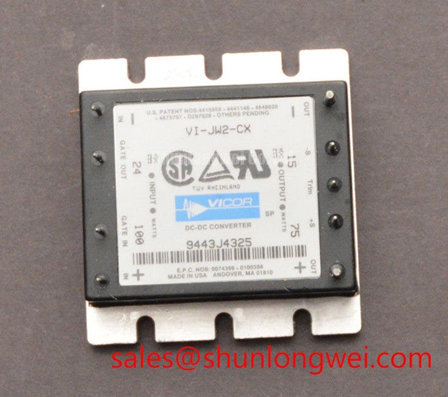
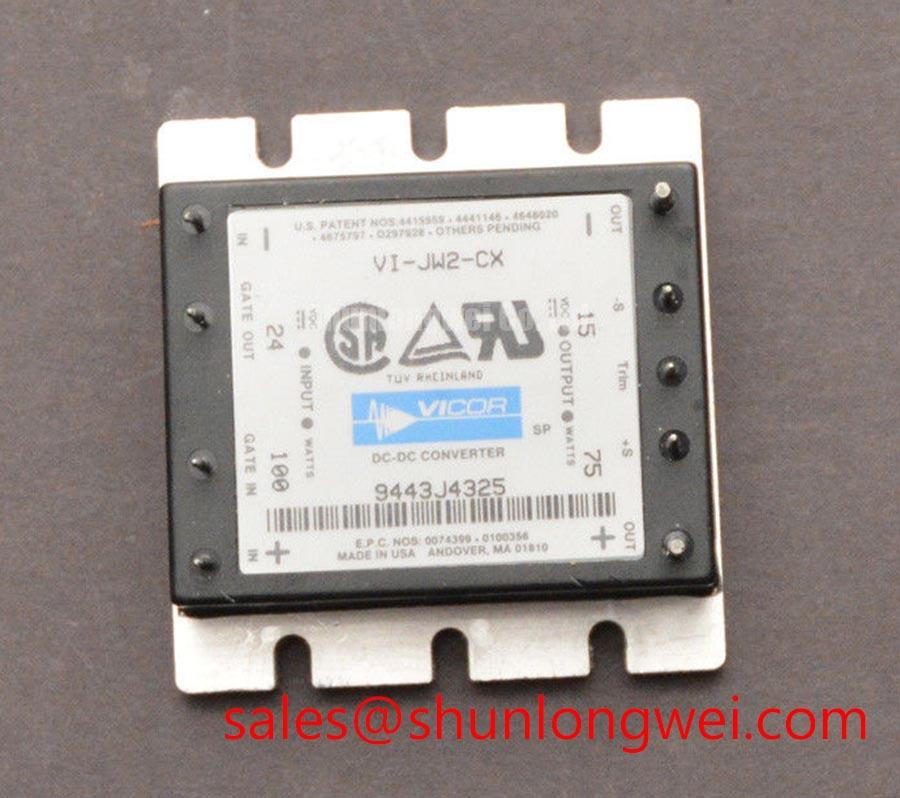
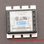
| Model | VI-JW2-CX |
|---|---|
| Manufacturer | Vicor |
| Product category | DC-DC converter |
| Physical format | Brick module |
| Input and output ratings | Numerical voltage and current ratings are not established by the supplied product specifications. |
Probe the VI-JW2-CX input at its connection to the drive when a deceleration command causes the control electronics to reset. Record the input and output waveforms alongside the DC-link waveform, using measurement methods appropriate to the equipment’s hazardous voltages. A reset that coincides with braking activity does not, by itself, identify the converter as faulty: disturbance can reach its input through the auxiliary supply, wiring, or shared return path.
The VI-JW2-CX is a Vicor DC-DC converter, not a braking IGBT or ballast resistor. In a heavy-duty variable frequency AC motor drive, the braking chopper and resistor form a separate power path that must be evaluated against the motor’s deceleration energy and the drive’s DC-link limits. As a Design Consideration, compare chopper command timing, resistor voltage, and DC-link rise before attributing a control-power interruption to the converter. The drive designer determines braking-component ratings and validates them under the equipment’s operating conditions.
Keep the distinction visible during a repair. A control supply can remain steady while the braking path develops an abnormal waveform; the reverse is also possible. If the drive contains a power-stage device such as FS225R12KE3, inspect its role on the equipment schematic rather than treating its ratings or connections as specifications for VI-JW2-CX. For waveform work on the converter itself, compare input disturbance, output response, and load current at the same event. That sequence gives the repair engineer evidence about where the interruption begins.
VI-JW2-CX Circuit Protection: Checking Ratings Before a Brick-Module Replacement
Measure the disconnected supply path for an unexpected low resistance, then check the converter’s input polarity and connector positions against the drive wiring diagram. A cold resistance reading is an initial screen, not a pass-or-fail verdict for a DC-DC converter: connected capacitors and downstream circuits can affect the meter reading. Inspect mounting contact, terminal condition, and evidence of local heating before fitting another module.
The supplied product information describes the VI-JW2-CX as a brick-module DC-DC converter but does not establish numerical input, output, current, or isolation ratings. Do not turn the phrases “standard industrial rating” and “standard operating current” into electrical limits. For an in-place replacement, match the exact model and verify the required ratings, pin assignments, mechanical fit, and control connections against the equipment documentation and the applicable Vicor specification. Physical similarity alone cannot establish electrical interchangeability.
Parallel IGBT current sharing is a separate power-stage question. A positive temperature coefficient of collector-emitter saturation voltage, where documented for the IGBT under consideration, can assist static sharing; it cannot establish dynamic balance without examining gate-drive paths and busbar symmetry. Neither that characteristic nor a Kelvin-emitter terminal should be attributed to VI-JW2-CX. The same boundary applies when reviewing MG75H6EL1 during a broader drive repair: its device function and compatibility must be assessed independently, not as a substitute for this DC-DC converter.
Field alert: Isolate the drive and verify that stored DC-link energy has discharged before disconnecting the brick module or probing its wiring.
VI-JW2-CX Control-Power Checks Around Isolated Gate Drivers
Capture the gate-driver supply waveform at the driver board when unexplained switching pulses or undervoltage trips appear. Measure at the load as well as at the VI-JW2-CX output connection; a stable converter output at one point cannot rule out a voltage drop or disturbance farther along the harness. Compare the affected channel with a known-good channel under the same operating state, and check whether the fault aligns with power-stage switching.
Optocouplers and coreless-transformer drivers are properties of the drive’s gate-driver circuitry, not identified features of this converter. As a Design Consideration, an isolated driver’s barrier rating and common-mode transient immunity must suit the installed power stage and its measured switching environment. No isolation voltage or transient-immunity figure for VI-JW2-CX is established here, so those figures must not be assigned to it or used as replacement criteria without a device-specific specification.
Trace the converter’s supply and return connections through the actual board layout. Keep noisy power paths from coupling into sensitive control wiring where the equipment design permits, then verify the result with waveforms during switching rather than relying on a quiet benchtop reading. If a driver output changes without a corresponding command, inspect its local supply, reference connection, and input signal before changing the converter. Gate resistance, active clamping, Miller effects, and diode reverse recovery can shape switching behavior, but their component values and protection settings belong to the documented power stage, not to an assumed internal circuit of VI-JW2-CX.
Thermal contact also deserves a physical check when a fault develops after warm-up. Inspect the module’s mounting interface and nearby airflow without assuming that a hot enclosure identifies the failed part. The broader heat-flow principles discussed in The Advanced Thermal Management Revolution can inform that inspection; the mounting method and allowable temperatures still need to come from the applicable equipment and component documentation.
VI-JW2-CX Operational Boundaries During Motor-Output Filter Troubleshooting
Measure the converter’s output at the control load while the drive changes switching state, then inspect motor-terminal waveforms separately if trips occur with a long motor cable. A disturbance at the motor terminals and a dip on the control rail may share a switching event without sharing a single cause. Keep the two measurements distinct so that a motor-output problem does not become an unsupported diagnosis of the VI-JW2-CX.
Reflected-wave stress on long motor leads is a system-level Design Consideration. Cable length, impedance, switching edges, and termination affect terminal voltage; an output sinusoidal filter and a dv/dt reactor address different waveform requirements. Select neither from the brick module’s physical format. The drive designer should evaluate motor insulation requirements, cable conditions, filter compatibility, and measured terminal peaks before choosing or changing an output network.
Control algorithms also change when and how the inverter is commanded, but they do not define this converter’s electrical ratings. The alpha-beta transformation describes a coordinate treatment of motor quantities, while direct torque control describes a motor-control approach. Those concepts can help an engineer interpret drive behavior during a test; neither establishes that VI-JW2-CX is suitable for a particular drive or output-filter arrangement.
For the final fault check, repeat the measurement at the converter input, converter output, driver-board supply, and motor terminals under the same commanded operating condition. Compare the sequence of waveform changes with the equipment schematic and its protection log. That preserves the practical boundary of this part: VI-JW2-CX supplies DC-DC conversion, while braking, gate switching, and motor-output filtering remain separately rated subsystems.