


Content last revised on April 24, 2026
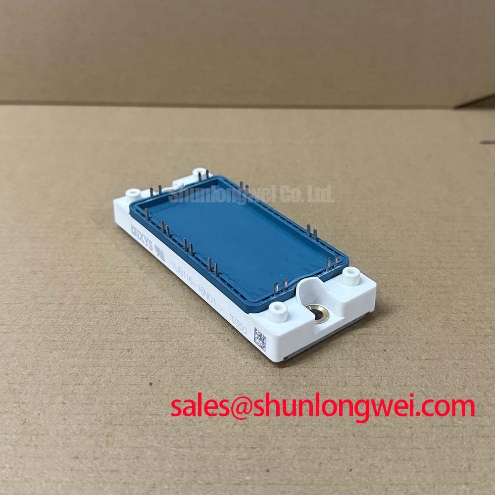
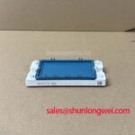
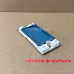
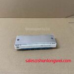
VUB116-16NO1: Integrated Rectifier & Brake Chopper Module
VUB116-16NO1 Rectifier with Brake Chopper: Technical Overview
The IXYS VUB116-16NO1 streamlines power stage design by consolidating a three-phase rectifier and an IGBT brake chopper into a single, compact module. This integrated approach significantly simplifies the architecture of AC motor drives and switched-mode power supplies. How does this integration reduce design complexity? By combining two critical functions, it reduces component count, minimizes PCB footprint, and shortens assembly time. With its robust electrical characteristics and built-in isolation, the VUB116-16NO1 provides a foundation for efficient and space-conscious power conversion systems.
Streamlining Power Stages: Application Verticals
The dual-function nature of the VUB116-16NO1 makes it a highly effective solution for applications where both AC-DC rectification and management of regenerative energy are required within a constrained space. Its design eliminates the need for separate rectifier and chopper circuits, reducing both wiring complexity and potential points of failure.
- AC Motor Drives: Serves as the complete front-end for Variable Frequency Drives (VFDs) and servo drives, rectifying the AC input and managing braking energy during motor deceleration. What is the main benefit of the VUB116-16NO1? It simplifies design by combining a rectifier and brake chopper.
- Switched-Mode Power Supplies (SMPS): Ideal for power supplies that require active braking or must safely dissipate energy from the DC bus under certain load conditions.
- Battery Charging Systems: Can be implemented in chargers where control over the DC link voltage is necessary, especially in systems with regenerative capabilities.
- Power In-feed for Robotics: Provides a compact power interface for robotic arms and automation systems, where rapid acceleration and deceleration cycles generate significant regenerative currents.
For AC drives up to ~55 kW handling regenerative energy, the VUB116-16NO1's integrated topology is the optimal choice for minimizing assembly complexity.
Comparative Data for Informed Component Selection
Evaluating the VUB116-16NO1 requires a clear view of its specifications relative to other solutions. The following table provides factual data to support your design and procurement decisions. This comparison is intended to empower your analysis by presenting key parameters side-by-side, without making direct recommendations. For systems with different voltage or current requirements, the VUB72-16NO1 is a related component within the same product family for consideration.
| Parameter | IXYS VUB116-16NO1 | Alternative Module (Illustrative) | Engineering Implication |
|---|---|---|---|
| Module Configuration | Three-Phase Rectifier + Brake Chopper (IGBT) | Three-Phase Rectifier Only | Integrated solution simplifies BoM and assembly vs. a two-module approach. |
| IdAV (Rectifier, TC=80°C) | 116 A | ~120 A | Defines the maximum average DC output current capability for the rectifier stage. |
| VRRM | 1600 V | 1600 V | Indicates suitability for high-voltage AC mains, including 690V industrial lines. |
| VISOL | 3600 V~ | 3000 V~ | Higher isolation voltage simplifies heatsink mounting and enhances system safety. |
Architectural Breakdown: The Integration Advantage
The core value of the VUB116-16NO1 lies in its internal architecture, which is engineered for simplification and reliability. By housing both the input bridge and the brake chopper within a single electrically isolated package, the module directly addresses several engineering challenges.
A key element is its use of a Direct Copper Bonded (DCB) ceramic substrate. This construction provides excellent thermal conductivity while ensuring high electrical isolation. What is the isolation voltage of this module? It provides 3600V~ electrical isolation via its DCB substrate. The benefit of this design is twofold: it facilitates efficient heat transfer to a common heatsink and removes the need for separate, often fragile, insulating pads during assembly. This integration reduces stray inductance between the rectifier and the chopper, which can be a source of voltage overshoot in discrete designs. For more information on the principles of thermal management in power modules, a deep dive on unlocking IGBT thermal performance can provide valuable context.
Strategic Impact: Compacting the Future of Power Conversion
The move toward more integrated power electronics, as exemplified by the VUB116-16NO1, is a direct response to market demands for smaller, more cost-effective, and reliable systems. As industrial automation and machinery become more sophisticated and compact, the space available for power electronics shrinks. Modules like this are not just components; they are system-level solutions that enable designers to achieve higher power density. By reducing assembly steps, minimizing inventory (one part number instead of two or more), and simplifying thermal design, this integrated approach contributes directly to a lower total cost of ownership (TCO) and a faster time-to-market for new products. This aligns with the broader push for efficiency and modularity in modern industrial equipment design.
VUB116-16NO1 Core Electrical & Thermal Specifications
The following parameters are critical for system design and integration. This curated list highlights the key performance indicators that define the module's operational capabilities, focusing on the metrics most relevant to its role in simplifying power conversion stages. For a complete list of specifications, please refer to the official datasheet.
| Parameter | Value |
|---|---|
| Maximum Repetitive Reverse Voltage (VRRM) | 1600 V |
| DC Output Current (IdAV @ TC=80°C) | 116 A |
| Collector-Emitter Voltage, Brake Chopper (VCES) | 1200 V |
| DC Collector Current, Brake Chopper (IC25 @ TC=25°C) | 115 A |
| Max. Junction Temperature (Tvjmax) | 150 °C |
| Isolation Test Voltage (VISOL, 50/60 Hz, RMS, t=1min) | 3600 V~ |
Download the VUB116-16NO1 Datasheet
Frequently Asked Questions
By integrating the brake chopper, the module eliminates the need for an external chopper circuit and its associated wiring. This reduces the PCB footprint, lowers assembly costs, simplifies the Bill of Materials (BoM), and minimizes stray inductance between the DC link and the chopper, which can mitigate voltage spikes during braking events.
The high isolation voltage, achieved through a DCB substrate, allows the module to be mounted directly to a grounded heatsink without requiring an additional insulating layer. This simplifies the mechanical assembly, improves thermal transfer compared to using external pads, and enhances overall system safety and reliability. For further reading, explore our guide on decoding power module datasheets.
For optimal heat dissipation, the module's baseplate must be mounted on a flat, clean heatsink surface with a thin, uniform layer of thermal grease. It is crucial to follow the torque specifications provided in the datasheet for the mounting screws to avoid mechanical stress on the ceramic substrate and ensure a low-resistance thermal path.
As power systems continue to evolve towards greater density and efficiency, the strategic adoption of integrated modules like the IXYS VUB116-16NO1 will become increasingly vital. Investing in such components enables engineering teams to not only meet the technical requirements of today but also to build scalable, cost-effective platforms prepared for the next generation of automated and electrified systems.