Content last revised on February 25, 2026
VBO13-14NO2 IXYS Single Phase Rectifier Bridge: Engineering for High-Voltage Reliability
How can power supply designers ensure stable input rectification in industrial environments where 400V or 480V mains are subject to frequent transient voltage spikes? This technical challenge often leads to premature component failure if the selected rectifier lacks sufficient blocking voltage margin. The VBO13-14NO2, an IXYS Single Phase Rectifier Bridge, addresses this specific vulnerability by providing a high 1400V reverse blocking capacity in a compact, PCB-mountable ECO-PAC1 package.
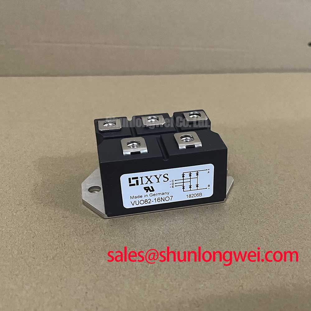
The VBO13-14NO2 is a planar passivated diode bridge optimized for efficiency and long-term thermal stability. With a maximum average forward output current of 15A (at Tc = 100°C) and a blocking voltage of 1400V, it offers a significant safety overhead for 3-phase line rectification or high-voltage single-phase inputs. It eliminates the need for complex discrete diode arrangements while maintaining superior heat dissipation characteristics. What is the primary benefit of its planar passivation? It ensures ultra-low leakage current and protects the junction against ionic contamination, preventing catastrophic thermal runaway in high-temperature industrial settings. For 400V line inputs requiring compact PCB rectification, the VBO13-14NO2 with its 1400V blocking capacity provides an essential safety margin.
Frequently Asked Questions
Addressing Core Concerns in Power Rectification
How does the 1400V blocking voltage rating impact the reliability of a 480V AC input system?
In a 480V RMS system, peak voltages reach approximately 680V. Standard 800V or 1000V rectifiers leave little margin for "dirty power" transients common in industrial grids. The 1400V rating of the VBO13-14NO2 provides a buffer of over 700V above the peak operating voltage, drastically reducing the risk of avalanche breakdown during switching surges or grid fluctuations.
What are the thermal advantages of the ECO-PAC1 package over standard discrete bridge rectifiers?
The ECO-PAC1 package utilized by the VBO13-14NO2 features an isolated copper base plate. This construction allows for direct mounting to a heatsink, providing a much lower thermal resistance from junction to case (RthJC) compared to standard plastic-potted discrete components. This ensures that the 15A current capacity is maintained even in high-ambient temperature enclosures.
Key Parameter Overview
Decoding the Specs for Enhanced Thermal Reliability
The following table summarizes the critical electrical and thermal characteristics of the VBO13-14NO2 based on the manufacturer's technical documentation.
| Parameter Symbol | Technical Specification | Engineering Value |
|---|---|---|
| V_RRM | Max repetitive reverse voltage | 1400V |
| I_dAV | Average forward current (Tc=100°C) | 15A |
| I_FSM | Max non-repetitive surge current (10ms) | 200A |
| V_F | Forward voltage drop (at 15A) | 1.36V |
| T_VJ | Operating junction temperature range | -40 to +150°C |
| V_ISOL | Isolation voltage (AC, 1 min) | 3000V |
Technical Deep Dive
Planar Passivation and Thermal Path Optimization
The internal architecture of the VBO13-14NO2 relies on IXYS planar passivated silicon chips. To understand the significance of planar passivation, consider it like a high-performance sealant on a specialized mechanical gasket; it prevents electrical "leaks" (leakage current) even when the system is under high pressure (voltage). By utilizing a silicon dioxide layer to protect the P-N junction, the VBO13-14NO2 achieves extreme stability in its reverse blocking characteristics over its entire -40°C to +150°C operating range.
From a thermal perspective, the module utilizes a DCB (Direct Copper Bonding) substrate. This technology reduces the number of thermal interfaces between the silicon die and the external heatsink. In high-power designs, every millikelvin per watt (K/W) counts. The low thermal resistance of the ECO-PAC1 package allows engineers to minimize heatsink size while maintaining the 15A rating, which is critical for the trend toward miniaturized SMPS and VFD input stages. Furthermore, the 3000V isolation rating ensures compliance with international safety standards for industrial machinery, eliminating the need for additional isolation barriers.
Application Scenarios & Value
Precision Rectification for Industrial Power Stages
The VBO13-14NO2 is specifically designed for input stages where space is limited but high-voltage robustness is mandatory. A typical engineering scenario involves a compact Variable Frequency Drive (VFD) for a 2.2kW motor. The input stage must handle the initial charging of the DC bus capacitors, which subjects the rectifier to significant surge currents. The 200A I_FSM rating of the VBO13-14NO2 ensures it can handle these repetitive inrush events without degradation.
Beyond VFDs, this module is a staple in high-reliability Uninterruptible Power Supplies (UPS) and battery charging systems. In these applications, the 1.36V low forward voltage drop directly contributes to system efficiency, reducing the cooling burden on the enclosure fans. For systems requiring higher power integration, such as three-phase rectification with an integrated brake chopper, the VUB72-16NO1 offers a higher current handling capacity while maintaining the same IXYS reliability standards. For more complex power control requirements, engineers may also consider the MCC200-16IO1 thyristor module.
Understanding the nuances of semiconductor selection is critical for long-term reliability. For further insights into selecting the right components for power conversion, refer to our guide on IGBT vs MOSFET vs BJT selection or explore the Power Semiconductor Selection Guide.
Additional Engineering FAQs
Does the VBO13-14NO2 require a snubber circuit for normal operation?
While the module is inherently rugged due to its planar passivation, a small Snubber Circuit (RC network) is often recommended in high-inductance environments to suppress voltage spikes caused by parasitic line inductance during diode commutation. This further protects the 1400V V_RRM limit.
Can the VBO13-14NO2 be wave-soldered?
Yes, the pins are designed for standard PCB through-hole mounting. The package design allows for reliable soldering while the thermal baseplate remains accessible for mechanical attachment to a heatsink.
As industrial power systems move toward 800V platforms and increased energy density, the role of robust rectification becomes even more critical. The VBO13-14NO2 represents a strategic choice for engineers who prioritize thermal margin and high-voltage safety. By integrating advanced IXYS chip technology into a compact footprint, it enables the design of resilient power converters that meet the demands of modern automation and green energy infrastructure.