Content last revised on September 10, 2026
DC-Bus Operating Voltage Headroom Derating for Single Event Burnout (SEB) Immunity
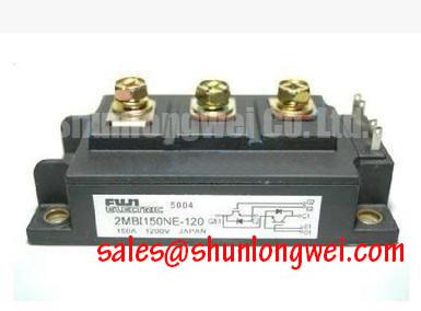
Operating electric material handling platforms, heavy automated guided vehicles (AGVs), and industrial warehouse forklifts subjects power conversion hardware to demanding operational environments. In elevated logistics hubs, regional distribution centers situated at altitudes exceeding 2000 meters, and cold-storage operations, power semiconductors encounter environmental stress profiles that differ significantly from standard indoor bench test conditions. For the 2MBI150NE-120 dual IGBT module from Fuji Electric, which features a maximum collector-emitter rating of VCES = 1200V (Official Datasheet Specification) and a continuous DC collector current of IC = 150A at Tc = 25°C (Official Datasheet Specification), establishing a resilient DC-bus headroom strategy is essential for continuous plant uptime.
High-altitude deployment exposes silicon power devices to an increased flux of terrestrial cosmic neutrons. Atmospheric neutron interaction within the reverse-biased high-voltage drift region of an energized IGBT can trigger localized avalanche multiplication, culminating in destructive Single Event Burnout (SEB). Because cosmic-ray-induced failure rates escalate exponentially with both applied DC electric field intensity and altitude, relying on the absolute maximum voltage rating during continuous operation creates substantial long-term reliability risks. In standard forklift traction architectures fed by rectified mains or elevated battery strings, operating nominal DC-bus potentials between 600V and 750V provides the necessary margin against cosmic-ray SEB while leaving sufficient headroom for inductive turn-off switching transients and regenerative braking energy absorption.
Preventative engineering protocols detailed in the Field Engineer’s Handbook highlight that mitigation of field failures requires addressing both steady-state line potentials and high-frequency voltage spikes. In material handling drive systems, abrupt load rejections—such as rapid mechanical braking or sudden mast-lift relief valve activation—dump substantial energy back onto the DC rail. To suppress transient surges, layout engineers should place metal oxide varistors (MOVs) and low-inductance polypropylene film snubber capacitors across the positive and negative DC terminals in close physical proximity to the module pins. Creepage and clearance distances along the PCB busway must also be derated according to altitude correction multipliers defined in IEC 60664-1 to prevent surface tracking and partial discharge under humid cold-storage condensation cycles.
| Operational Condition / Parameter | Datasheet Rating / Design Baseline | Plant Maintenance Recommendation |
|---|---|---|
| Collector-Emitter Breakdown Voltage (VCES) | 1200V (Official Datasheet Specification) | Derate nominal DC-bus to ≤ 750V for SEB protection |
| Continuous Collector Current (IC, Tc=25°C) | 150A (Official Datasheet Specification) | Monitor dynamic thermal cycling during heavy acceleration |
| Pulsed Collector Current (ICP, 1ms) | 300A (Official Datasheet Specification) | Limit acceleration peak current thresholds in drive software |
| Isolation Voltage (Vis, AC 1 min) | 2500V (Official Datasheet Specification) | Perform annual insulation leakage tests across baseplate |
Optimizing Heatsink Contact Pressure and Surface Roughness for Minimum R_th(c-s)
Thermal management in industrial traction drive cabinets directly determines the operational life of the internal silicon dies and substrate assemblies. The 2MBI150NE-120 exhibits a junction-to-case thermal resistance of Rth(j-c) = 0.11 °C/W per IGBT element (Official Datasheet Specification). However, the total thermal path from junction to ambient is heavily governed by the contact interface between the module's copper baseplate and the extruded aluminum or liquid-cooled heatsink. Surface irregularities, air gaps, and uneven mechanical pressure increase the case-to-heatsink thermal resistance (Rth(c-s)), causing excessive silicon junction temperatures during repetitive forklift start-stop cycles.
Achieving optimal thermal transfer requires meticulous mechanical preparation of the heatsink mounting surface. The heatsink surface flatness must remain within 50 µm across a 100 mm span, with a surface roughness of Rz ≤ 10 µm (General Industry Design Consideration for Power Modules). Prior to mounting, technicians must clean the interface with isopropyl alcohol to remove oxidation residues, machining oils, and airborne particulate matter. Thermal Interface Material (TIM)—whether silicone-based thermal grease or advanced phase-change compounds—must be applied evenly using a precision stencil or roller to maintain a wet film thickness strictly between 50 µm and 80 µm. Excessive thermal paste application creates a thermal barrier that increases Rth(c-s), while insufficient paste leaves micro-voids filled with stagnant air, which acts as a thermal insulator.
⚠️ Maintenance Note: During semi-annual electrical cabinet overhauls, inspect the perimeter of the 2MBI150NE-120 baseplate for thermal grease pump-out or dry-out cracking caused by cyclic thermal expansion. Measure the terminal contact temperature under rated motor load using a calibrated thermal imaging camera. Any localized temperature rise exceeding 15°C above the heatsink reference baseline indicates thermal interface degradation or loose mounting hardware, requiring immediate dismounting, surface refinishing, and TIM reapplication.
Baseplate mechanical fastening must follow a strict two-stage torque sequence using calibrated torque wrenches to prevent internal ceramic substrate warping. For the standard M5 mounting screws, apply an initial pre-torque of 0.5 N·m in a diagonal cross-pattern across the mounting holes. Once the pre-torque settles the thermal grease layer, tighten the fasteners to the final torque of 2.5 N·m to 3.5 N·m (General Industry Design Consideration for M5). This uniform clamping force prevents mechanical shear stress on internal semiconductor interconnections, a critical factor detailed in studies on Wire Bonding Metallurgical Reliability in Power Semiconductor Modules regarding thermal fatigue prevention under cyclic traction loads.
Active Miller Clamp Implementation & Parasitic Capacitive Turn-On Prevention
In high-speed variable frequency drives (VFDs) controlling forklift traction motors, parasitic switching phenomena can induce destructive shoot-through faults across the inverter phase leg. The 2MBI150NE-120 exhibits a typical turn-off time of toff = 1.5 µs (Official Datasheet Specification) and a gate-emitter threshold voltage range of VGE(th) = 5.5V to 8.5V (Official Datasheet Specification). When the complementary upper or lower IGBT switches on with high dv/dt, displacement currents flow through the collector-gate parasitic Miller capacitance (Cres / Cgc) of the unenergized device into its gate drive circuit.
If the gate impedance of the off-state device allows this displacement current to develop a transient voltage across the external gate resistor exceeding VGE(th), the uncommanded device enters partial conduction. This parasitic capacitive turn-on causes momentary cross-conduction shoot-through across the DC bus, producing localized current spikes, excessive thermal dissipation, and potential dielectric breakdown. Mitigating this risk requires dedicated layout practices combined with robust active gate drive circuits.
- Negative Gate Bias: Supplying a dedicated negative turn-off bias (typically -5V to -15V) to the gate terminal provides an expanded voltage margin below VGE(th), absorbing dv/dt induced charge without reaching the conduction threshold.
- Active Miller Clamp Circuitry: Implementing a low-impedance internal or external Miller clamp switch connects the gate directly to the negative rail (or emitter return) once the gate voltage drops below approximately 2.0V during turn-off, bypassing the turn-off gate resistor.
- Gate Loop Inductance Minimization: Positioning gate driver stages directly above or within centimeters of the module pins using tightly twisted pairs or paired stripline PCB layouts minimizes gate circuit loop inductance.
For large industrial transport vehicles requiring expanded current capacity beyond 150A, engineers often assess multi-module paralleling or migration to higher-capacity packages. For systems requiring higher current handling without altering bus topologies, the related 2MBI450UE-120 offers an elevated collector current capability of 450A within a 1200V rating, allowing engineers to maintain thermal and switching headroom across larger traction payloads.
High-Speed Fault Management: V_CE(sat) Desaturation Sensing Circuitry
Direct output short circuits, stator insulation puncture, and motor cable pinch events represent constant hazards in warehouse traction equipment. Under normal saturation conditions, the 2MBI150NE-120 maintains an on-state saturation voltage of VCE(sat) = 2.1V (Typical) / 2.8V (Max) (Official Datasheet Specification). When an un-cleared hard short occurs across the load terminals, the IGBT desaturates and exits its low-impedance conduction region, rapidly driving VCE toward the DC-bus rail voltage while carrying massive fault currents well in excess of its pulsed collector rating of ICP = 300A (Official Datasheet Specification).
Under short-circuit safe operating area (SCSOA) constraints, the IGBT must be detected and fully isolated within a maximum fault duration of 10 µs. A dedicated desaturation (DESAT) detection circuit continuously monitors the collector-emitter voltage across the module during on-state conduction. A high-voltage blocking diode connected from the DESAT pin of the driver IC to the IGBT collector isolates the driver from the high DC bus voltage during off periods. Upon turn-on command, an integrated blanking capacitor charges via an internal current source, providing a blanking filter window (typically 1.5 µs to 3.0 µs) to prevent false tripping caused by the initial VCE falling edge.
If VCE remains above the programmed threshold (typically set between 6.5V and 8.0V) after the blanking period expires, the fault comparator triggers an immediate hardware shutdown. Abruptly interrupting short-circuit currents creates extreme di/dt across stray bus inductances, generating severe overvoltage transients that can exceed the 1200V breakdown limit. Therefore, the gate driver must execute a Two-Stage Soft Turn-Off (STO), gradually reducing the gate voltage over several microseconds to safely quench fault currents within the Safe Operating Area without inducing destructive flyback spikes.
In safety-critical drive assembly lines, validating component placement and structural integrity relies heavily on inline quality control measures, such as Automated Optical Inspection (AOI) in Semiconductor Assembly. Combining precise driver protection circuits with high-speed semiconductor fuses ensures total equipment isolation during severe terminal faults, protecting downstream electronics and minimizing industrial plant downtime.