
Content last revised on September 10, 2026
Mitigating Hard Switching Transients via Active Desaturation Soft Shutdown
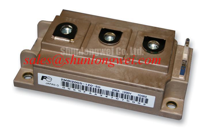
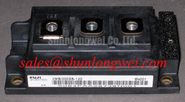
Operating multi-axis CNC machines and robotic arm drives demands tight dynamic control under relentless acceleration cycles. In high-inertia servo systems, inverter output faults—such as motor terminal flashovers, line-to-line shorts, or phase-to-ground isolation breakdowns—present severe hazards to silicon dies. The Fuji Electric 2MBI200SB-120 dual IGBT module integrates a collector-emitter blocking voltage rating of 1200V and a continuous collector current rating of 200A (at TC = 80°C), making it a standard building block in 380V to 480V three-phase industrial equipment.
When high-current fault transients occur, the module relies on a rated short-circuit withstand time (tsc) of 10µs under test conditions of VCC = 600V and Tj = 125°C. Managing this critical window requires an active desaturation (DESAT) protection circuit paired with a structured two-stage soft turn-off (2SSTO) routine rather than an abrupt hard shutdown.
| Parameter | Specification / Condition | Official Rating | Plant Engineering Interpretation |
|---|---|---|---|
| VCES | Collector-Emitter Voltage (Tj = 25°C) | 1200V | Sets peak blocking headroom across high-voltage industrial utility mains. |
| IC | Continuous DC Collector Current (TC = 80°C) | 200A | Defines full continuous drive capacity under standard forced-air/liquid cooling. |
| VCE(sat) | Saturation Voltage (Tj = 125°C, VGE = 15V) | 2.6V (Typical) | Controls steady-state conduction loss and localized silicon thermal rise. |
| Rth(j-c) | Junction-to-Case Thermal Resistance (per IGBT) | 0.083 °C/W | Governs heat extraction efficiency into the module copper baseplate. |
| PD | Maximum Power Dissipation (TC = 25°C) | 1500W | Absolute thermal ceiling for silicon die power dissipation per switch. |
| Viso | Isolation Voltage (AC, 1 minute) | 2500V | Ensures primary electrical isolation against the grounded machine chassis. |
| tsc | Short-Circuit Withstand Time (VCC = 600V, Tj = 125°C) | 10µs | Maximum permissible detection-to-quenching duration during terminal short events. |
In practice, Type-I short circuits (occurring when the device switches into an existing dead short) and Type-II short circuits (occurring while the device is already fully saturated) push the collector current far beyond nominal ratings into deep desaturation. If the gate driver cuts the gate voltage from +15V directly to -8V at high current, the steep di/dt interacting with stray parasitic loop inductance (Lσ) creates an inductive voltage spike governed by ΔV = -Lσ · (di/dt). This transient easily exceeds the 1200V VCES breakdown ceiling.
Implementing a two-stage soft turn-off reduces the gate voltage to an intermediate level (around 6V to 8V) for 3µs to 5µs, bleeding off channel charge and lowering the di/dt slope before full negative clamp isolation. To protect the sensing mechanism from high voltage during normal off-states, high-voltage fast recovery blocking diodes must be paired with low-leakage bypass capacitors. Standard design guidelines emphasize separating the high-current power emitter trace from the auxiliary Kelvin emitter terminal on the driver printed circuit board. Routing the Kelvin emitter directly back to the gate driver IC reference plane prevents large load current di/dt drops from contaminating the gate drive loop.
Cosmic Ray Robustness: Voltage Derating Curves across 2000m-4000m Altitudes
Industrial machinery deployed in elevated manufacturing hubs encounters higher terrestrial neutron flux than sea-level installations. Atmospheric cosmic rays generate high-energy secondary neutrons capable of striking silicon lattice structures, triggering localized electron-hole plasma tracks that can lead to catastrophic Single Event Burnout (SEB). Unlike standard thermal runaway, SEB occurs instantaneously within the depletion region when high DC-link voltage stress is sustained over long operating hours.
For standard 1200V silicon architectures operating on 400V–480V AC utility grids, the rectified intermediate DC-bus voltage typically sits between 560V and 750V. At sea level, the Failure-in-Time (FIT) rate due to SEB remains negligible. However, as installation altitude increases toward 2000m to 4000m, atmospheric neutron density climbs exponentially. Maintaining plant reliability targets demands systematic DC-bus voltage derating or active DC-link regulation to preserve safe silicon field-strength margins.
Minimizing gate ringing and transient overshoots during dynamic switching at high altitudes is essential. Gate driver peak sourcing and sinking current requirements must be calculated to prevent uncontrolled oscillatory turn-on:
Ig(peak) = (VGE(on) - VGE(off)) / (Rg(ext) + Rg(int))
Applying an asymmetrical gate resistance configuration—where turn-off resistance Rg(off) is tuned slightly higher than turn-on resistance Rg(on)—damps high-frequency oscillation across parasitic gate loop inductance while keeping turn-off switching energy (Eoff) within safe operational boundaries. Sizing the bootstrap capacitors properly ensures sufficient charge delivery during repetitive high-frequency PWM cycles without allowing the high-side floating gate supply voltage to sag.
When engineering replacement modules across legacy machinery or comparing lower-voltage sub-assemblies, evaluating components like the 2MBI200KB-060 provides practical context regarding how voltage class margins alter transient susceptibility across differing utility tiers. Reference bench verification steps and diagnostic techniques are outlined in detail inside our Field Engineer’s Handbook.
Thermal Feedback & VCE(sat) Positive Temperature Coefficient Equalization
Heavy duty-cycle positioning servos in robotic transfer lines inflict extreme thermal swings on power modules. The Fuji Electric 2MBI200SB-120 features a typical saturation voltage VCE(sat) of 2.6V at Tj = 125°C under VGE = 15V. Crucially, modern silicon IGBT dies exhibit a positive temperature coefficient at higher current densities, where saturation voltage rises moderately alongside junction temperature.
This positive temperature coefficient acts as an intrinsic self-balancing mechanism across parallel internal cells. As one section of the die heats up, its local forward resistance increases, naturally diverting current toward cooler silicon regions. However, this dynamic stabilization only functions effectively if external mechanical mounting and heat-sinking conditions maintain uniform thermal resistance (Rth(j-c) = 0.083 °C/W).
⚠️ Field Alert: In manufacturing facilities running 24/7 production, thermal paste migration and matrix pump-out represent primary causes of mid-life IGBT degradation. Baseplates subjected to repetitive thermal expansion cycles experience dry-out of conventional silicone-based thermal grease within 36 to 60 months, resulting in localized thermal hotspots and premature bond wire lift-off.
Advanced module packaging strategies continue evolving, adopting methods such as Flip-Chip Packaging with Copper Pillar Bumps for Low Parasitic Inductance and exploring Isotropic Conductive Adhesive (ICA) for Solderless Component Interconnections to stabilize thermal interfaces. Plant maintenance protocols for the 2MBI200SB-120 require strict physical preparation during regular equipment overhauls:
- Heatsink Surface Flatness: Verify heatsink planarity within ≤50µm per 100mm span, with a surface roughness of Rz ≤ 10µm. Remove all oxidation, metal burrs, and industrial particulate.
- Thermal Interface Compound: Apply a uniform, screen-printed layer of high-stability thermal grease at a controlled thickness of 50µm to 80µm. Excessive paste increases thermal resistance, while insufficient grease leaves air voids.
- Fastener Torque Sequence: Tighten M5 mounting bolts incrementally in a cross-pattern. Initial hand-tightening to approximately 0.5 N·m ensures even compound dispersion, followed by final torque calibration to 2.5–3.5 N·m using a calibrated torque wrench.
- Terminal Torque Control: Calibrate main power terminal connections to the recommended 2.5–3.5 N·m to avoid mechanical stress fractures on internal terminal footings.
Sizing Braking Resistors and Chopper Transistors for High-Dynamics Servos
High-speed pick-and-place robots and multi-axis CNC spindles generate massive regenerative energy during rapid deceleration profiles. Mechanical inertia transforms the driving servomotor into an electrical generator, directing current back through the inverter freewheeling diodes into the DC-link capacitor bank. If unmanaged, the bus voltage surges toward the 1200V maximum threshold of the inverter stage.
Preventing bus overvoltage faults requires an active dynamic braking chopper circuit. In custom power topologies, single-switch chopper stages such as the 1MBI200SA-120B are frequently paired alongside the dual half-bridge 2MBI200SB-120 to manage discharge sequencing into high-power ballast resistors.
Calculating the minimum dynamic braking resistance (Rbrake(min)) prevents overcurrent tripping of the chopper switch while ensuring sufficient braking deceleration torque:
Rbrake(min) = VDC(brake_trip) / IC(peak_chopper)
For an active chopper trip threshold set at 750V DC on a 460V system, utilizing a 200A peak-rated chopper requires a ballast resistance strictly greater than 3.75Ω. The continuous power rating of the braking resistor must be dimensioned to handle repetitive kinetic duty cycles:
Presistor(cont) = (Jtotal · (ωinitial2 - ωfinal2) / (2 · tcycle)) · ηregen
Where Jtotal represents combined motor and load inertia, ω denotes angular velocity, and tcycle is the operational cycle time. The freewheeling diodes within the 2MBI200SB-120 must comfortably absorb the continuous reverse recovery stress (Qrr) during repetitive motor regeneration without entering thermal runaway.
Routine cabinet maintenance must include periodic inspection of enclosure intake air filters and blower fans. In CNC shop environments containing atomized machining coolants and fine conductive metal dust, clean air paths and moisture-sealed enclosures prevent tracking currents across high-voltage insulation barriers (Viso = 2500V AC).