

Content last revised on September 25, 2026
Assembly Integrity & Layout Architecture for CM20TF-12H During Hard Switching
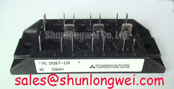
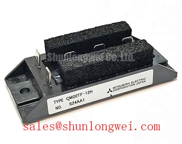
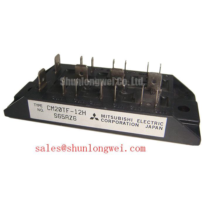
With the inverter isolated and the DC link discharged, begin by checking the CM20TF-12H terminal area for loose hardware, heat damage, cracked encapsulation, and abnormal cold state resistance between accessible power terminals. The supplied official product data identifies this Mitsubishi Electric power device as a 600.0 V, 20.0 A Module. Confirm that these ratings match the removed unit and the equipment documentation before any replacement work begins.
| Parameter | Official Specification |
|---|---|
| Manufacturer | Mitsubishi Electric |
| Part number | CM20TF-12H |
| Rated voltage | 600.0 V |
| Rated current | 20.0 A |
| Package | Module |
Hard switching faults are often influenced by the complete commutation loop rather than by the power module alone. As a Design Consideration, keep the gate drive return path controlled and minimize loop inductance where fast current changes can create turn off overshoot. Check the DC link connection, snubber components, busbar fastening, and gate driver routing before attributing repeated module stress to the replacement part.
For protection circuits intended to distinguish Type I and Type II short circuit events, the system engineer should validate the response timing against the applicable safe operating limits from the original equipment documentation. A staged soft turn off approach can be evaluated where an abrupt gate shutdown could create unacceptable inductive voltage rise. Oscilloscope measurements at the installed inverter, using an appropriate high voltage probing method, remain the practical way to verify switching peak voltage and gate behavior.
When a repair bill of materials requires a separate review of related Mitsubishi module families, the CM300DXDX1-24A should be evaluated only against the original circuit topology, mechanical footprint, gate drive requirements, and thermal conditions. A shared manufacturer name does not establish direct replacement compatibility.
CM20TF-12H Circuit Protection & Reliability in Isolated Gate Drive Systems
An isolated gate driver supply should be inspected as part of the CM20TF-12H fault assessment. Measure whether its output remains stable during command transitions, then compare the gate signal at the driver output with the signal at the module terminals. A waveform that changes materially between these points may indicate a layout, grounding, connector, or drive supply issue that needs correction before the inverter returns to service.
Isolation barrier performance and common mode transient immunity are system level Design Considerations, not published CM20TF-12H specifications in the supplied data. Designers should verify the required galvanic isolation category, transient immunity capability, and creepage arrangement from the machine safety design and gate driver documentation. These checks help prevent noise induced gate pulses when the switching node moves rapidly.
Complementary gate commands also require an interlock strategy. The dead time buffer must be established by the driver and control system, then verified under the actual load, bus voltage, temperature, and switching conditions. Do not infer a suitable timing value from the module current rating alone. If the power stage includes a front end rectifier or related power section, the CM100DY-12E is a relevant product record for a separate topology and specification review.
For manufacturer level background on power semiconductor product families, consult Mitsubishi Electric Power Semiconductors and High Power Modules. Equipment level protection behavior must still be checked against the original drive schematic and control board revision.
Transient Dynamics & Electrical Design Around CM20TF-12H Gate Control
A suspected cross conduction event should be investigated with both gate to emitter waveforms and the switching node waveform captured during a controlled test. Negative gate bias and an active Miller clamp are alternative gate control approaches that system designers may evaluate to reduce unwanted turn on caused by high switching voltage slew rates. Neither approach should be assumed to be required or supported by a specific drive board without confirming the original gate driver design.
As an Engineering Recommendation, inspect gate resistor placement, driver return routing, terminal cleanliness, and connector retention before changing gate circuit parts. A damaged gate resistor, weak driver supply, or poorly seated control connector can produce symptoms that resemble a module problem. Verify the measured waveforms against a known good phase or documented service waveform where available.
The MOV and snubber network should also be checked as a coordinated overvoltage control path. A MOV that has been thermally stressed, a disconnected capacitor, or a high resistance bus connection may alter transient behavior. ⚠️ Field Alert: Disconnect control and power cables only after confirming that stored DC link energy has been safely discharged.
For engineers comparing resonant and half bridge behavior during appliance related inverter troubleshooting, Resonant Topologies in Home Appliances provides a useful reference point for evaluating commutation conditions. It should not be used as a substitute for the original compact inverter or CNC spindle drive schematic.
CM20TF-12H Operational Boundaries and Heatsink Contact Verification
Before fastening the CM20TF-12H to a heatsink, clean both mating surfaces and inspect the base contact area for debris, corrosion, raised marks, or visible distortion. Apply thermal interface material as a thin, uniform layer sufficient to fill surface irregularities without creating excessive separation. Thermal interface thickness and contact pressure are Design Considerations determined by the heatsink flatness, mounting hardware, thermal material documentation, and machine duty cycle.
Tighten mounting screws in a progressive cross pattern so the module settles evenly against the heatsink. Follow the original equipment torque requirement and screw specification rather than applying a generic torque value. Uneven loading can impair thermal contact and complicate diagnosis because a temperature related failure may appear only after the machine reaches normal operating load.
When evaluating pulse heating, use the applicable transient thermal impedance information from the correct manufacturer documentation rather than relying only on steady state heatsink temperature. The system engineer should compare measured load behavior, switching frequency, ambient conditions, and cooling airflow against the equipment thermal design. For rare event reliability topics such as radiation related semiconductor effects, use source specific material such as Radiation Hardening background; no CM20TF-12H field failure rate or lifetime claim should be inferred without applicable manufacturer or test evidence.