Content last revised on September 25, 2026
FSBB20CH60C Inspection and Replacement Assessment
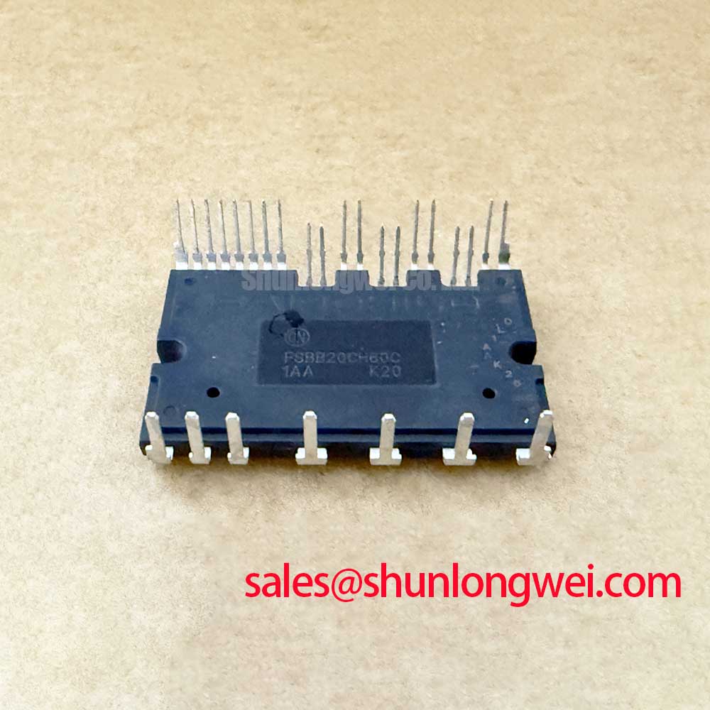
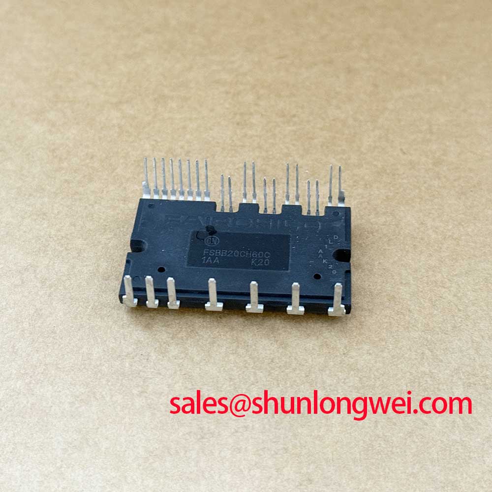
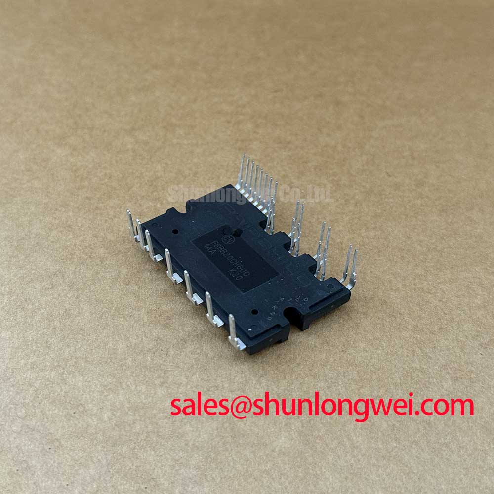
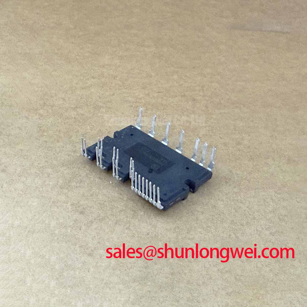
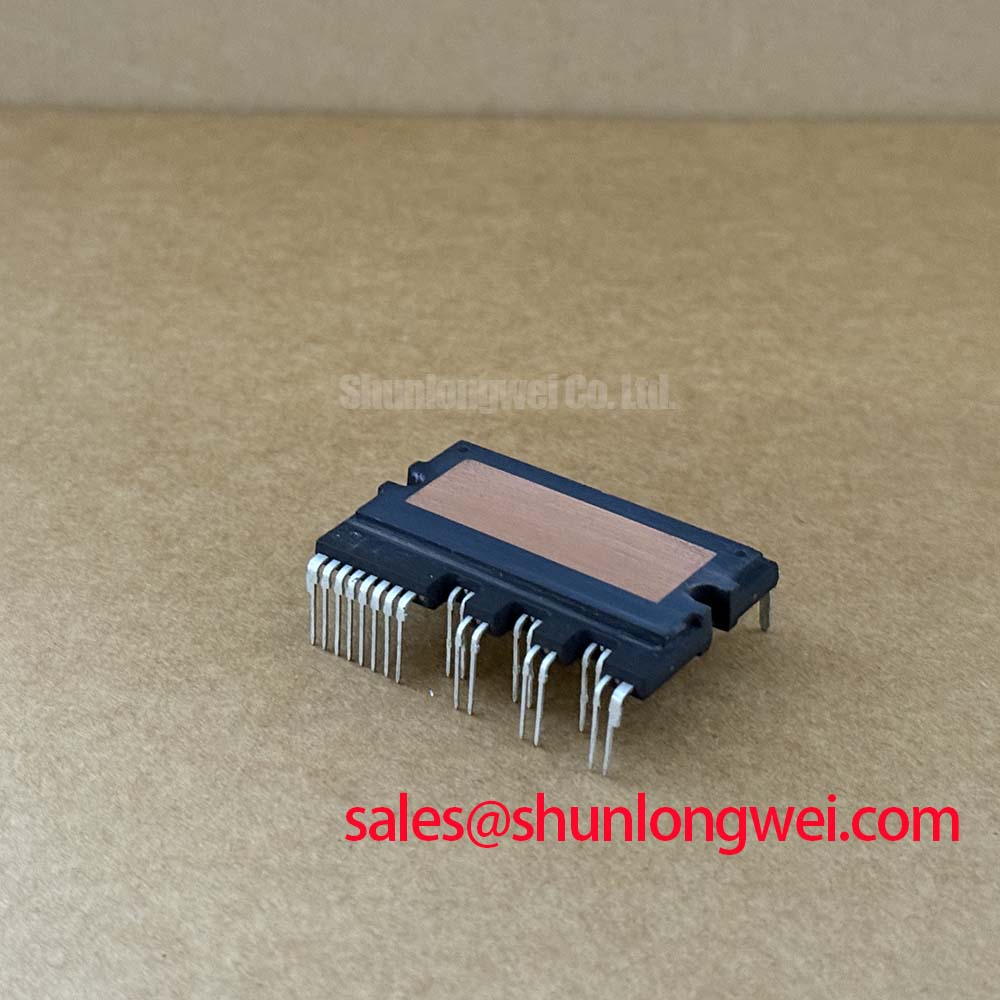
With the DC link discharged and isolated, first compare the cold-state terminal relationships of the removed FSBB20CH60C against the equipment schematic and a known-good drive assembly before reconnecting any gate-drive wiring. The available official product identification is clear: this onsemi (formerly Fairchild Semiconductor) power semiconductor is supplied as a Module, with an official rated voltage of 600.0 V and official rated current of 20.0 A. These ratings establish the device-level electrical boundary for repair assessment; they do not define the completed inverter's permissible DC-link voltage, switching frequency, overload profile, insulation coordination, or thermal design.
For incoming inspection, record the case condition, terminal condition, connector engagement, and identification marking before applying power. A diode-mode check across accessible power paths can identify a gross short or an unexpected open relationship, but the observed reading must be compared with the circuit topology and a known-good reference. Meter polarity, parallel paths on the control board, and stored charge in surrounding capacitors can all alter what the meter displays. Isolate the module from the surrounding circuit where the service procedure allows it.
💡 Bench Tip: Use ESD-controlled handling and preserve cold-state readings from the known-good assembly, because direct comparison is more useful than treating one diode-mode value as a universal pass or fail threshold.
| Attribute | Value | Classification |
|---|---|---|
| Product model | FSBB20CH60C | Official product identification |
| Manufacturer | onsemi (formerly Fairchild Semiconductor) | Official product identification |
| Rated voltage | 600.0 V | Official Datasheet Specification |
| Rated current | 20.0 A | Official Datasheet Specification |
| Package | Module | Official Datasheet Specification |
FSBB20CH60C Thermal-Electrical Optimization: Optocoupler and Digital Isolator Gate-Drive Tuning
Before evaluating a replacement FSBB20CH60C in a traction inverter, identify the isolation method already used by the original control board. Some equipment uses optocoupler-based gate-drive paths, while other assemblies use digital isolators with isolated driver stages. The two approaches have different propagation behavior, output impedance, supply requirements, and susceptibility to layout coupling. A module rating of 600.0 V and 20.0 A does not establish the required isolation rating or common-mode transient immunity of the drive circuit. The system integrator should verify these properties from the original inverter documentation and the driver component documentation.
A practical bench sequence begins with the control board unpowered. Confirm that the driver connector and its mating interface are free of displaced contacts, residue, cracked solder joints, or strain caused by harness movement. Then trace the driver supply return and gate-drive return paths from the schematic or board layout. A long shared return path can couple power-stage current changes into a driver reference and create a waveform that resembles an unintended command. That observation does not prove a module defect. It calls for measurement at the driver output and at the module interface with the correct isolated probing method.
Design Consideration: reinforced isolation barriers, creepage, clearance, and common-mode transient performance must be assessed as a complete drive-system requirement. The relevant values depend on the control architecture, pollution degree, insulation system, PCB construction, enclosure, and applicable equipment standard. Do not assign an isolation capability to this module from its voltage rating alone. The Infineon IGBT Modules and Discretes portfolio provides broader manufacturer context for power semiconductor product families, while the exact interface requirements remain a property of the equipment design.
On a repaired forklift traction controller, examine the gate command at both low-energy functional test conditions and controlled switching conditions. A gate waveform that differs from the known-good channel can result from a damaged driver, return-path coupling, inadequate driver supply decoupling, a connector issue, or measurement setup limitations. Check the probe reference arrangement before assigning the result to the power module. Designers should keep gate-drive loops compact where layout permits, separate sensitive control routing from high-current commutation paths, and validate switching behavior against the actual DC-link and motor conditions.
Where another power position in the same industrial system is being reviewed, the FZ3600R12HP4 is a separate module reference that can be evaluated from its own published documentation. It should not be treated as electrically or mechanically interchangeable with the FSBB20CH60C without checking topology, voltage class, current duty, package interface, driver compatibility, and thermal path.
FSBB20CH60C Operational Boundaries: Evaluating VCE Desaturation Fault Management
Desaturation protection belongs to the driver and protection architecture around the module, not to the published 600.0 V and 20.0 A identity data alone. In a traction inverter repair, confirm how the original controller detects abnormal collector-emitter behavior, how it communicates a fault to the controller, and how the driver removes gate drive. A desaturation event can be associated with a load-side short circuit, incorrect gate command, driver supply collapse, wiring damage, or a measurement error. It should be investigated through captured waveforms and the original protection sequence rather than inferred from one visible fault code.
Design Consideration: a fault response has to control the tradeoff between reducing current quickly and limiting the inductive voltage rise created when current is interrupted. A staged or soft turn-off strategy is commonly evaluated in IGBT drive systems for that reason, but its timing, resistance network, clamp behavior, and fault thresholds are system-determined. They must be verified against the applicable safe-operating information for the specific device and the actual inductance of the inverter loop. Do not transfer protection settings from a different module, even when the voltage class appears similar.
When an inverter contains parallel power paths, static current balance depends on the complete assembly. The temperature dependence of on-state voltage can influence sharing, but it does not remove the need for symmetric electrical paths, comparable cooling conditions, matched drive behavior, and measurement under the intended duty. A useful diagnostic comparison is to capture current and voltage behavior across equivalent paths while confirming that sensor calibration and probe placement are consistent. Asymmetry may point to busbar geometry, connection resistance, cooling variation, timing skew, or a driver problem.
For background on the system issues involved in parallel module operation, consult the Infineon IGBT Paralleling Application Note. Its discussion should be applied as a design reference, not as evidence that the FSBB20CH60C is approved for a particular parallel arrangement. In the same way, Evolution of Negative Off-Bias Gate Drive Circuits can inform an engineering review of gate turn-off behavior, while the original driver documentation must determine whether that approach is appropriate for the installed system.
For electric material handling and forklift low-voltage traction equipment, replacement assessment should include the battery contactor sequence, pre-charge operation, current sensor path, motor cable condition, and controller fault logging. The device can be evaluated for this application category because its official ratings are known, but equipment compatibility remains subject to the original inverter's electrical, mechanical, and thermal requirements.
FSBB20CH60C Thermal-Electrical Optimization: Planar Symmetrical Busbar Geometry and Practical Tuning
Inspect the DC-link connection and busbar stack before condemning a FSBB20CH60C after an overvoltage-related event. Darkened insulation, loose hardware, displaced laminate layers, uneven contact pressure, or a disturbed capacitor connection can alter the commutation loop. During turn-off, the peak device voltage is influenced by the DC-link voltage plus the voltage developed across stray loop inductance as current changes. This relationship explains why a physically small change in conductor routing or capacitor placement can materially change the measured switching waveform.
Engineering Recommendation: minimize commutation-loop inductance to suppress turn-off inductive overshoot, place the effective DC-link energy storage close to the switching loop where the system architecture permits, and preserve a symmetric supply and return geometry. The required inductance target, snubber selection, capacitor technology, and damping values are system-determined. They should be established through controlled switching tests that verify peak voltage margins against the actual DC-link voltage, load current, temperature, and probe bandwidth. The official 600.0 V rating is a component specification, not a substitute for that validation.
A planar busbar arrangement can reduce loop area when its outgoing and return conductors are closely coupled. It also requires disciplined mechanical assembly. Inspect mating surfaces for flat, clean contact areas and confirm that the hardware sequence matches the equipment documentation. If spring hardware or double-sided cooling fixtures are present, treat their clamping force and compression behavior as assembly-specific requirements. Do not apply a generic torque value unless the equipment or module mounting documentation specifies the fastener, washer stack, thread engagement, and required torque.
Long motor leads deserve separate attention during forklift controller commissioning. Motor-cable impedance and propagation delay can create reflected voltage at the motor terminals. The familiar possibility of reflected peaks approaching twice the incident step is a transmission-line behavior under particular termination conditions, not a guaranteed waveform for every cable installation. Designers should assess cable length, cable construction, motor insulation system, switching edge behavior, and any output filtering through measurement at appropriate locations. A motor-terminal waveform and an inverter-terminal waveform answer different questions.
Where a repair requires an alternative part to be considered, the FS200R06KL4 is a related power-module listing for independent comparison. Its part number alone does not establish replacement suitability. Compare its official ratings, internal topology, pinout, package dimensions, mounting interface, driver requirements, protection behavior, and thermal characteristics against the original equipment before making a design or procurement decision.
Field Diagnostics and Commissioning: Dynamic Power-Loss Dissipation in FSBB20CH60C Topologies
Commissioning starts with the cooling interface and the evidence available from the removed assembly. Check whether the module mounting plane, heat sink, interface material, fasteners, and airflow path match the original arrangement. A poor thermal interface can elevate junction temperature even when static electrical checks show no obvious abnormality. Conversely, a module that fails a cold-state comparison may have experienced an electrical fault whose root cause is upstream of the cooling system. Keep electrical and thermal evidence separate until waveform and mechanical inspection support a connection.
The official identity data for the FSBB20CH60C provides no published transient thermal impedance values in the supplied specification set. Therefore, it is not valid to calculate a junction-temperature margin, pulse overload capability, or allowable repetitive overload from the 600.0 V and 20.0 A ratings alone. A multi-resistance thermal model can be used only when the relevant manufacturer thermal data and the actual case-to-heat-sink conditions are available. This is an Engineering Calculation, and its quality depends on the input data, duty cycle, switching loss, conduction loss, interface condition, and coolant or airflow conditions.
For a controlled return-to-service procedure, technicians should first validate insulation and continuity according to the equipment service method, then confirm low-energy control operation before exposing the power stage to normal traction load. Capture DC-link behavior, gate commands, current feedback, and fault responses with appropriately rated instruments. Compare equivalent channels where the topology permits. Unexpected temperature rise, uneven current behavior, abnormal gate waveform shape, or recurring fault events may justify stopping the test and checking the driver, capacitor bank, busbar assembly, motor cable, current sensing, and cooling path.
Do not use unverified runtime hours, failure-rate figures, altitude derating claims, EMC assertions, or lifetime predictions to judge this module. Those conclusions require applicable manufacturer documentation, equipment-level compliance evidence, and measured operating conditions. The practical decision record should retain the original part identification, the official 600.0 V and 20.0 A ratings, cold-state comparison results, installation observations, and commissioning waveforms so that the next service decision is based on traceable evidence.