
Content last revised on September 10, 2026
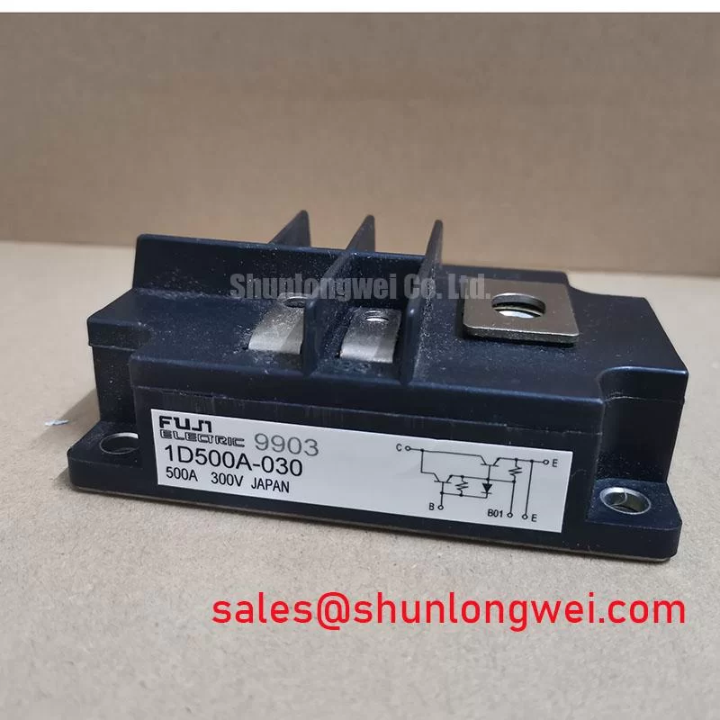
Fuji Electric 1DI500A-030 IGBT Module: Reliable High-Current Performance for Industrial Systems
How do design engineers balance extreme high-current demands with compact thermal management in low-frequency industrial applications?
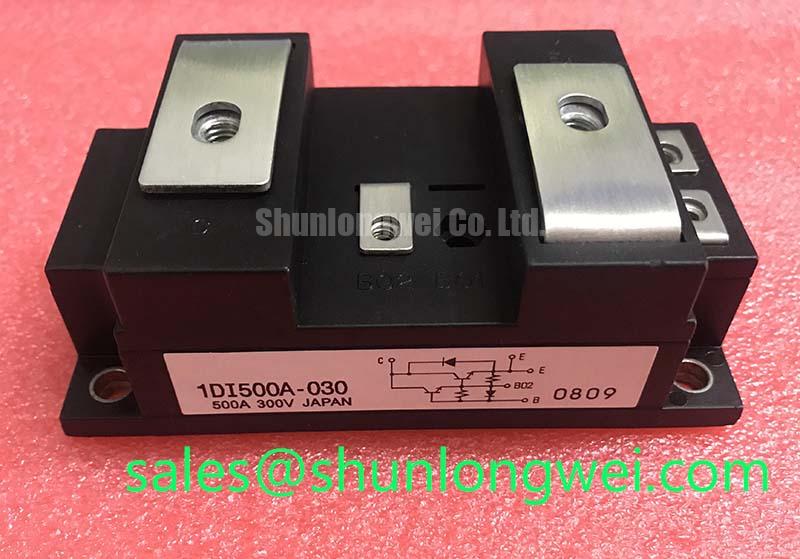
The 1DI500A-030 is a high-power insulated semiconductor module designed to deliver stable power switching and transient robustness in motor control and general-purpose inverter applications. Top Specifications: 300V | 500A | 2500V AC isolation voltage. Key Benefits: Excellent safe operating area; integrated free-wheeling diode protection. Can the 1DI500A-030 handle motor startup inrush current safely? Yes, its 1000A peak current rating and robust safe operating area allow it to manage transient inrush currents without thermal runaway.
Frequently Asked Questions
Addressing Critical Integration and Operational Inquiries
How does the 2500V AC isolation voltage rating affect system safety and layout?
What is the isolation rating of the module? It provides 2500V AC isolation between terminals and the baseplate. This rating acts as a barrier, protecting low-voltage logic circuits from high-voltage terminal surges during switching.
What is the significance of the built-in free-wheeling diode?
How does the built-in diode protect circuits? It clamps inductive voltage spikes to prevent transistor breakdown during turn-off. In motor drivers, it provides a safe freewheeling path for back-EMF currents.
How does the 1000A peak current rating benefit motor drives?
A typical drive motor draws high inrush currents during startup. The 1000A peak rating provides a 2x headroom over the continuous 500A limit, allowing the system to absorb short-term surges without triggering protection circuits.
What are the thermal management requirements given the junction temperature limit of 100°C?
With a maximum junction temperature of -20 to +100°C, heat dissipation is a primary design constraint. Engineers must utilize high-performance thermal interface materials and ensure heatsink mounting flatness to maintain baseplate temperatures well below the limit under full-load operation.
Can I test this module using a standard multimeter in the field?
Yes, field technicians can check the integrity of the junctions using standard diode and resistance test modes. For step-by-step procedures, refer to our guide on How to Test an IGBT Module with a Multimeter.
Key Parameter Overview
Decoding the Specifications for Enhanced System Performance
To support engineering evaluation and modeling, the table below outlines the core electrical and thermal parameters of the 1DI500A-030. For further details on parameters like saturation voltages and thermal resistance, engineers should consult the IGBT Module Selection Guide.
| Parameter | Value | Engineering Interpretation |
|---|---|---|
| Collector-Emitter Voltage | 300V (VCES) | Specifies the maximum DC bus voltage, suitable for low-voltage industrial rectifiers. |
| Continuous Collector Current | 500A (IC) | Defines the continuous current handling capability at a standard baseplate temperature. |
| Peak Collector Current | 1000A (ICP) | Indicates transient current capacity to handle start-up surges. |
| Isolation Voltage | 2500V AC (Viso) | The maximum dielectric strength between baseplate and terminals for galvanic safety. |
| Junction Temperature | -20 to +100°C (Tj) | Indicates the allowable thermal window for safe semiconductor junction operation. |
| Storage Temperature | -40 to +125°C (Tstg) | Determines the safe limits for shipping, handling, and system storage. |
Technical & Design Deep Dive
Understanding the Darlington Configuration and Built-In Protections
The 1DI500A-030 utilizes a classic Darlington transistor structure integrated with a free-wheeling diode in a single insulated package. While modern designs often compare different topologies, referencing an IGBT vs MOSFET vs BJT selection guide highlights how Darlington configurations provide high current gain at lower switching frequencies.
To understand its electrical robustness, think of its isolation voltage rating as a pressure-resistant dam. The 2500V AC isolation rating acts like a concrete wall preventing high-voltage surges on the power terminals from breaching the control side, protecting weak control electronics. Additionally, the pulse current capacity of 1000A operates similarly to an automotive shock absorber. During starting or inductive switching events, the module absorbs transient energy spikes without failing.
Designing gate drivers for Darlington modules requires providing sufficient base current to achieve full saturation. Insufficient drive current can lead to increased saturation voltage and overheating, which is critical given the module's -20 to +100°C junction temperature limit.
Application Scenarios & Value
Achieving High-Current Reliability in Harsh Industrial Environments
For heavy-duty DC choppers requiring 500A continuous current under 300V, this insulated module is the optimal choice.
This module is highly suited for high-power, low-frequency industrial applications. Typical use cases include uninterruptible power supplies (UPS), servo drives, and NC machine tools.
For instance, when designing servo drives for CNC machining spindles, engineers face severe start-up surges. A spindle motor drawing 350A continuously can pull well over 700A during rapid acceleration. The 1DI500A-030 solves this challenge with its transient tolerance of 1000A peak current. This headroom prevents thermal breakdown during the high-torque starting phase. Combined with the integrated free-wheeling diode, it effectively clamps the inductive spikes generated during motor deceleration, eliminating the need for bulky external snubber networks.
For systems requiring even higher current capacity under similar voltage classes, the related 1D600A-030 offers a rating of 600A.
From an integration perspective, utilizing the 1DI500A-030 requires careful planning of the gate drive layout. Keeping gate lead loops short and using twisted pairs helps mitigate electromagnetic interference from the high collector currents. Ensuring baseplate flatness remains within 50 micrometers during heatsink mounting is essential to maintain thermal contact resistance and guarantee long-term field reliability.