Content last revised on October 21, 2026
Benchtop Waveform Tuning: Mitigating Stress via Desaturation Detection on 1MBI400V-120-50
Isolate the DC link, verify that stored energy has discharged, and compare collector-to-emitter and gate-to-emitter measurements before reconnecting the gate driver to a suspect 1MBI400V-120-50. Disconnect parallel circuit paths where necessary: a reading taken through a braking resistor, snubber, or adjacent switch can obscure the condition of the module itself. Cold measurements provide an initial screen, not proof of correct switching operation.
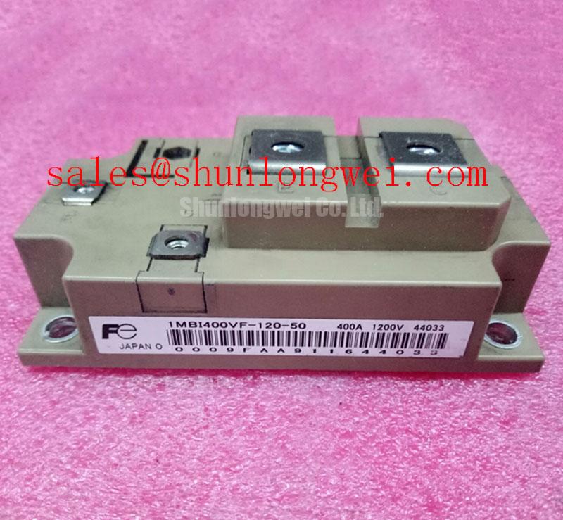
The Fuji Electric 1MBI400V-120-50 is an IGBT module with a 1200 V voltage rating and 400 A current rating, supplied in a Fuji Power Module package. These are Official Specification values; current-rating conditions, terminal assignments, dimensions, switching characteristics, and assembly limits require the applicable manufacturer datasheet. For replacement assessment, retain the complete part number, including its suffix, rather than matching only voltage and current.
Capture the gate-emitter voltage, collector-emitter voltage, and driver fault output together when investigating nuisance desaturation trips. As a Design Consideration, the useful distinction is whether the collector voltage remains elevated after a valid turn-on command or rises unexpectedly during established conduction. Either observation warrants checking the load path, driver supply, sensing circuit, and switching sequence before attributing the fault to the module.
Type-I short-circuit conditions describe switching into an existing fault; type-II conditions arise after conduction has started. Protection must address both where they are credible system faults. A microsecond-scale protection response is not, by itself, evidence of adequate short-circuit protection: the complete interval includes sensing blanking, detection, propagation, and controlled current extinction. Establish that interval against the device’s documented short-circuit safe operating area at the applicable voltage, gate drive, and junction temperature.
As an Engineering Recommendation, evaluate two-stage soft turn-off when abrupt fault shutdown produces excessive collector-voltage overshoot. The initial stage reduces fault current, while the subsequent stage completes turn-off. Their timing and gate-current profiles belong to the driver design and require waveform validation; extending shutdown indiscriminately can increase fault energy. Do not deliberately apply a power short circuit during routine field diagnosis.
Keep the desaturation sensing path separated from high-current commutation conductors and reference the driver through its intended emitter return. Creepage and clearance depend on working voltage, insulation architecture, and equipment requirements, rather than a universal spacing for this package. Use appropriately rated differential measurement equipment and compact probe connections to distinguish switching stress from measurement-induced ringing.
For a braking-chopper assessment, compare the circuit arrangement with Fuji Electric Brake Chopper IGBT Modules. This manufacturer resource provides topology context, not automatic confirmation that a particular module fits an existing chopper.
Assembly Integrity & Layout Architecture: Implementing Thermal Feedback for 1MBI400V-120-50
Check heatsink seating, interface condition, and the relationship between measured temperature and actual semiconductor loading before adjusting thermal shutdown thresholds. As a Design Consideration, a heatsink sensor responds differently from a junction-temperature estimate, particularly during short load bursts. Compare temperature trends under repeatable operating conditions rather than treating one surface measurement as the junction temperature.
A positive temperature coefficient of collector-emitter saturation voltage can assist static current sharing where the device characteristic is positive at the relevant operating point. It must not be assumed across the entire current range or treated as a confirmed feature of this exact module without its characteristic curves. Parallel operation also depends on matched cooling and conduction paths. Dynamic sharing requires attention to gate-loop symmetry, driver propagation, emitter-return impedance, and power-circuit inductance.
As an Engineering Recommendation, inspect complementary gate commands at both the controller and module terminals when checking dead-time protection. Command separation alone does not establish the absence of shoot-through: driver delays, current tailing, and induced gate voltage affect the actual overlap boundary. Set interlocking and dead time from the system’s switching behavior over its operating conditions, then inspect the resulting current waveform.
If the equipment uses temperature feedback, trace the sensor wiring and controller scaling before relying on its displayed value. The background explanation of negative temperature coefficient thermistors describes how resistance changes with temperature; it does not establish that the 1MBI400V-120-50 contains an integrated NTC sensor.
A cross-reference search may bring up 2MBI25L-120, but another Fuji part number is a comparison candidate, not a substitution approval. The following checks keep that distinction visible during procurement review.
| Selection check | 1MBI400V-120-50 | 2MBI25L-120 |
|---|---|---|
| Rated voltage | 1200 V — Official Specification | Consult datasheet |
| Rated current | 400 A — Official Specification | Consult datasheet |
| Package designation | Fuji Power Module | Consult datasheet |
| Replacement approval checks | Terminal map, circuit configuration, mounting, cooling, and driver compatibility | Evaluate each interface independently; no drop-in equivalence established |
1MBI400V-120-50 Circuit Protection & Reliability: Calibrating High-Speed Semiconductor Fuse I2t Melting
Compare a semiconductor fuse’s total clearing I²t with the protected circuit’s documented fault-withstand limits, rather than selecting it from normal current alone. As a Design Consideration, pre-arcing I²t covers only the melting interval; total clearing includes the subsequent arcing interval. DC voltage, prospective fault current, circuit time constant, and fuse placement influence interruption performance.
Do not assign the 1MBI400V-120-50 an undocumented I²t withstand value or assume that fuse coordination guarantees an intact module enclosure. Electronic protection and fusing have different roles: the driver may interrupt a controllable semiconductor fault, while a correctly selected fuse can isolate sustained fault current. Any claimed containment outcome requires evidence for the complete equipment assembly.
Trace the DC-link capacitor discharge path on the schematic. A fuse upstream of a local capacitor bank may not limit the initial energy delivered from that bank into a failed switch. Review branch placement, conductor routing, and the fault path with the equipment’s protection study. After an interruption, examine the bus connections, driver isolation, snubber network, and associated components before replacing only the open fuse.
In regenerative braking, the chopper controls energy transfer into the braking resistor; the fuse does not regulate that energy. As an Engineering Recommendation, assess resistor continuity, thermal protection, chopper commands, and DC-link feedback together. If 1MBI600LN-060 appears elsewhere in the power-stage documentation, evaluate its actual switching role independently rather than classifying it as a rectifier or compatible companion from the part number alone.
When assessing compatibility with a multi-megawatt offshore or onshore wind turbine full-scale converter, designers should verify the module’s assigned converter branch, electrical boundaries, cooling arrangement, and equipment approval requirements. That is an application assessment, not a claim that this module independently satisfies the converter’s power rating.
Transient Dynamics & Electrical Design: Preventing Terminal Overheating on 1MBI400V-120-50
Measure bolted-joint resistance with a four-wire micro-ohmmeter after isolating the module and establishing repeatable probe positions. As a Design Consideration, compare equivalent joints at similar temperatures and distinguish joint resistance from the resistance of the adjoining conductor. A universal acceptance threshold would overlook differences in terminal construction, contact area, and measurement placement.
Field Alert: Apply the documented terminal and mounting torques, and do not tighten a live connection to investigate a thermal hotspot.
Inspect contact surfaces, washer arrangements, busbar alignment, and mechanical loading before reassembly. Tightening cannot correct a busbar that pulls the terminal out of alignment. Use the specified thermal-interface material and assembly method, keeping contamination away from electrical contact surfaces. Record the connection condition so later measurements remain comparable.
During an authorized load test, compare thermographic profiles under repeatable current, cooling, and ambient conditions. Reflective metal surfaces can distort apparent temperatures, so interpret images alongside contact measurements and electrical loading. A localized hotspot may involve contact resistance, uneven current distribution, or nearby heat transfer; use the combined evidence rather than assigning a single cause from the image.
Operating period also matters: intermittent current and continuous loading produce different thermal trajectories. The discussion of Resonant Topologies in Home Appliances offers background on topology-dependent switching behavior, not a lifetime qualification for this module. For the repaired assembly, trend terminal temperature and connection resistance across the equipment’s approved duty cycle, then investigate any progressive departure from its established baseline.