Content last revised on August 28, 2026
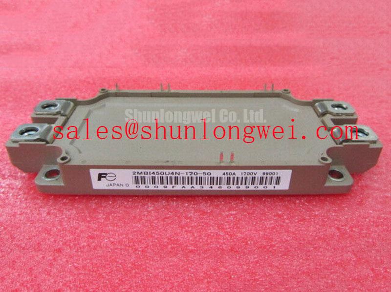
2MBI450U4N-170-50 Fuji Electric 1700V 450A IGBT Module
Engineers designing high-power industrial converters often grapple with a critical bottleneck: how to maintain high switching frequencies at 1700V levels without triggering catastrophic thermal losses or compromising voltage margins. The 2MBI450U4N-170-50, a dual IGBT module from Fuji Electric's established U4 series, directly addresses this challenge by optimizing the trade-off between collector-emitter saturation voltage and switching energy losses. This module provides a robust solution for systems operating on 690V AC lines where voltage spikes and high-efficiency power conversion are non-negotiable requirements.
1700V | 450A | U4 Series Technology
- Low Switching Loss: Advanced trench gate structure reduces total Eon and Eoff energy dissipation.
- Enhanced Reliability: High short-circuit withstand capability ensures survival during transient fault conditions.
What is the primary benefit of the U4 series' reduced switching loss? It allows for higher PWM frequencies which significantly reduces the size and cost of output filters. For 690V industrial drives requiring maximum efficiency and thermal headroom, this 1700V module is the optimal choice.
Frequently Asked Questions
Engineering Insights for High-Voltage Implementation
How does the 1700V Vces rating benefit 690V AC line applications compared to standard 1200V modules?
Operating on a 690V AC line results in a typical DC link voltage of approximately 975V to 1100V. A 1200V IGBT provides insufficient safety margin for inductive voltage spikes and surge transients. The 1700V rating of the 2MBI450U4N-170-50 offers the necessary 600V+ overhead to ensure long-term reliability and prevent voltage-induced dielectric breakdown in the silicon structure.
What is the impact of the U4 series gate-emitter capacitance on driver circuit design?
The U4 series technology is optimized for lower gate charge (Qg), which minimizes the peak current requirement for the Gate Drive. This allows engineers to use more compact gate driver ICs while maintaining fast transition times, effectively suppressing Switching Loss without increasing electromagnetic interference (EMI) signatures.
Key Parameter Overview
Decoding the Specs for Enhanced Switching Performance
The following technical specifications are derived from official documentation to support rigorous system-level evaluation. This data is essential for determining thermal dissipation requirements and protection logic settings.
| Basic Parameter | Specified Value | Engineering Significance |
|---|---|---|
| Collector-Emitter Voltage (Vces) | 1700V | Provides safety margin for 690V AC industrial power grids. |
| Collector Current (Ic) Continuous | 450A (at Tc=80°C) | Supports high-power Variable Frequency Drive (VFD) output stages. |
| Vce(sat) (Typical) | 2.30V (at Tj=125°C) | Low conduction losses facilitate simplified Thermal Management. |
| Short Circuit Withstand Time | 10µs (at Vcc=1000V) | Essential for protection coordination in Servo Drive systems. |
| Isolation Voltage (Viso) | 3400V AC (1 minute) | Ensures compliance with international safety standards for high-power equipment. |
Download the 2MBI450U4N-170-50 datasheet for detailed specifications and performance curves.
Technical Deep Dive
Analyzing the U4 Series Architecture for Loss Suppression
The 2MBI450U4N-170-50 utilizes Fuji’s fourth-generation trench gate field-stop (FS) technology. Think of switching losses in a high-voltage IGBT as frictional drag in a mechanical transmission; the faster you spin (or switch), the more energy is wasted as heat. By optimizing the carrier concentration profile near the emitter side, the U4 series minimizes the "tail current" during turn-off phases. This physical refinement significantly lowers the Switching Loss per cycle, enabling the module to operate at higher switching frequencies than conventional non-punch-through (NPT) designs.
Furthermore, the Safe Operating Area (SOA) of this module is specifically tuned for inductive load switching. In Solar Inverter applications, where the power factor can vary, the RBSOA (Reverse Bias Safe Operating Area) ensures that the device can safely turn off at twice its rated current under maximum DC link voltage. This ruggedness is a direct result of the refined Kelvin Emitter configuration within the package, which reduces the impact of parasitic stray inductance on the gate signal, preventing unintended oscillation or "false" turn-on during high dv/dt events. More technical details on the physics of these modules can be found in our deep dive into IGBT hybrid structures.
Application Scenarios & Value
Achieving System-Level Benefits in High-Voltage Industrial Power
A typical high-fidelity engineering challenge occurs in large-scale UPS (Uninterruptible Power Supply) systems, where rapid response to grid fluctuations is required. Using the 2MBI450U4N-170-50, engineers can design inverter stages that handle high PFC stage voltages while maintaining a compact footprint. The low Vce(sat) of 2.3V directly reduces the heatsink volume required, allowing for higher power density in modular rack-mounted systems.
In renewable energy applications, specifically Solar Inverters, the module's 1700V rating is critical for supporting 1000V DC bus architectures. By utilizing this module, designers can optimize the Switching Loss against system efficiency, meeting stringent energy regulations. For systems requiring even higher current handling within the same voltage class, the 2MBI1200U4G-170 offers a 1200A rating for centralized utility-scale projects. Alternatively, for high-frequency induction applications where different loss profiles are needed, engineers may compare these specs with 6MBI450V-170-50. For a broader framework on component choice, refer to our guide on IGBT selection beyond Vcesat.
Additional FAQ for Power Designers:
Does this module require a specific gate resistor (Rg) value for optimal switching?
Yes, the turn-on and turn-off characteristics are highly dependent on the Rg value. The data sheet provides recommended Rg ranges to balance Switching Loss and voltage overshoot. Deviating significantly from these values may exceed the RBSOA during peak load conditions.
What is the maximum junction temperature (Tj) for continuous operation?
The module is designed for a maximum Tj of 150°C, but for long-term reliability in industrial environments, designers typically target a maximum operating Tj of 125°C to provide a sufficient buffer against Thermal Management transients.
Strategic deployment of the 2MBI450U4N-170-50 allows for a significant reduction in total cost of ownership by balancing initial component cost with long-term energy savings and reduced cooling requirements. As global standards push for higher efficiency in motor drives and renewable energy, the U4 series remains a technologically relevant choice for 1700V power stages. To further understand the role of these components in the evolving power landscape, explore our analysis of the future role of IGBTs.