Content last revised on October 12, 2026
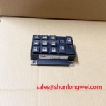
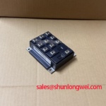
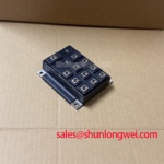
Field Diagnostics & Commissioning: Auxiliary Emitter Return Trace Separation in 6DI75MA-050 Topologies
Begin at the installed assembly, not at an assumed pinout. Trace the main current path from the DC link through the module terminals, then trace the control circuit’s emitter reference back to its driver. If the original equipment provides a separate auxiliary emitter connection, keep that sensing return distinct from the high-current emitter path as a Design Consideration. Shared conductor impedance can shift the voltage seen by the driver during switching and complicate diagnosis of ringing or unintended switching. A separate auxiliary connection is not established by the supplied 6DI75MA-050 product information, so the terminal diagram must decide whether this guidance applies.
For a board-level repair, inspect the return path for altered routing, damaged joints and unintended connections to power copper. Compare its continuity and physical route with a known-good assembly where one is available. Clearance to the power path should follow the equipment’s insulation and layout requirements rather than an assumed spacing for this module. During a controlled switching test, probe the control reference at the driver and at the documented module terminal using an appropriate measurement method. A difference between those waveforms may indicate coupling or return-path impedance; it does not, by itself, identify a defective module.
Replacement assessment also starts with topology and terminal mapping. The linked 7MBR75U2B060-50 is a separate candidate for comparison, not an established direct replacement for 6DI75MA-050. Check its device technology, electrical limits, pin arrangement, mounting interface and driver requirements against the original equipment before considering it. The same discipline matters in a forklift traction controller or other electric material-handling drive: the equipment application does not make two power modules interchangeable.
Field Diagnostics & Commissioning: Isolated Driver Supply and Protection in 6DI75MA-050 Topologies
Identify the control device on the equipment schematic before sizing an isolated driver supply. The supplied classification is Power Transistor / Darlington Module; it does not establish that 6DI75MA-050 uses an IGBT gate driver, a particular isolated DC-to-DC converter or desaturation protection. A bipolar Darlington drive circuit must be assessed using its documented drive-current and turn-off requirements. Applying an IGBT protection scheme without establishing the actual circuit could make fault behavior harder to interpret.
Where the existing system does use an isolated driver, an Engineering Recommendation is to check supply capacity against the driver’s measured demand during switching and fault handling. Review the converter’s isolation documentation, the board’s insulation arrangement and the driver’s common-mode behavior as separate matters. No reinforced-isolation withstand value or common-mode transient immunity rating is provided for this module, so neither can be inferred from its current rating. Fuji Electric’s power semiconductor and IPM product information provides broader manufacturer context, but the applicable limits for this part still require its own documentation.
If the installed controller has a desaturation detector, inspect its blanking and fault response against the controller and switch documentation; do not assign a fixed detection time to 6DI75MA-050. The same applies to staged or soft turn-off. Capture the fault input, drive output and module-terminal waveforms during a controlled bench test, then determine whether the protection sequence limits switching stress under the actual DC-link conditions. A fault indication may originate in sensing, wiring, supply behavior or the power stage, so preserve those possibilities until measurements distinguish them.
Power-path context helps keep that test focused. An upstream or auxiliary device such as QM200HA-HK may appear in a related equipment assessment, but its role must be established from that equipment’s schematic. Record the DC-link condition and the state of upstream switching before attributing a trip to the 6DI75MA-050 position.
Preventing Spurious Faults: Negative Gate Bias vs Active Miller Clamp Guidelines for 6DI75MA-050
Negative gate bias and active Miller clamps address unintended turn-on in gate-controlled devices. They should not be specified for 6DI75MA-050 solely because those techniques appear in an IGBT design guide: the supplied product classification identifies a Darlington module, and no gate-drive specification has been supplied. First verify the installed device technology and the original driver schematic. For this product page, the defensible integration question is whether the replacement preserves the equipment’s documented control interface and turn-off behavior.
If testing a separate, confirmed IGBT-based alternative, treat Miller coupling as a Design Consideration for that alternative. A low-impedance clamp or an appropriately designed off-state bias may help resist a voltage rise at its gate when the opposing switch changes state, but the choice depends on the actual driver, device limits and measured switching waveforms. Neither a negative-bias value nor clamp performance can be transferred to the Darlington-class 6DI75MA-050 by analogy.
For unexplained trips, capture the control signal, driver supply and switch-terminal voltages together. Compare the event with the commanded state and with a known-good signal path where possible. Keep the control return away from the high-current switching loop where the board design permits, to reduce coupled disturbance, then verify the result under the equipment’s operating conditions. Pro Tip: Do not connect a gate- or base-driver output to an unidentified 6DI75MA-050 terminal; confirm the original terminal diagram and drive circuit first.
Field Diagnostics & Commissioning: Junction-to-Case Thermal Network Simulation in 6DI75MA-050 Topologies
Start thermal assessment with measurements the equipment can support: case temperature near the module mounting interface, current waveform, duty cycle and the cooling condition during the fault or overload. The 75.0 A rated current (Official Specification) is not, on its own, a permissible pulsed-overload profile. The supplied information does not include junction-to-case transient thermal impedance, a maximum junction temperature or loss curves. Without those inputs, a numerical peak-junction calculation would imply precision the available data does not support.
A multi-RC thermal network can be useful once an applicable manufacturer thermal model and loss data have been obtained. As an Engineering Calculation, that model would use the measured time-varying dissipation and the documented transient thermal response to estimate junction temperature, then compare the estimate with the documented limit. Until those inputs are confirmed for 6DI75MA-050, use case-temperature trends and the condition of the heatsink interface to investigate differences between operating cycles, rather than declaring a junction-temperature margin.
Inspect mounting flatness, fastener condition and the thermal interface while the assembly is isolated. Follow the original equipment’s mounting instructions for fastening and interface-material application; neither a torque value nor a thermal-interface thickness is established by the supplied module information. Vibration in an electric material-handling vehicle makes the condition of the mounting arrangement worth checking, but a visible mounting defect should be evaluated alongside electrical loading and cooling measurements rather than treated as a complete explanation of a trip.
Packaging articles can inform that assessment without supplying missing facts about this part. Sintering describes a materials process, but it does not establish the die-attach material inside 6DI75MA-050. Similarly, the discussion of switching behavior in Resonant Topologies in Home Appliances can help frame topology-dependent loss questions; it does not establish this module’s intended application or thermal ratings. For the installed assembly, resolve the thermal question with the correct module data, measured loading and verified cooling path.