Content last revised on October 20, 2026
6MBP75VDA120-50 Operational Boundaries: Evaluating Drop-In Retrofit: Tuning Turn-On/Turn-Off Limits
I check the control connector against the original board schematic before treating a 6MBP75VDA120-50 replacement as a gate-resistor tuning exercise. An intelligent power module must be evaluated through its documented control interface, not approached as a bare IGBT with freely accessible gate terminals. Establish which switching characteristics the integrated driver determines and which adjustments the equipment manufacturer actually permits before changing the surrounding circuitry.
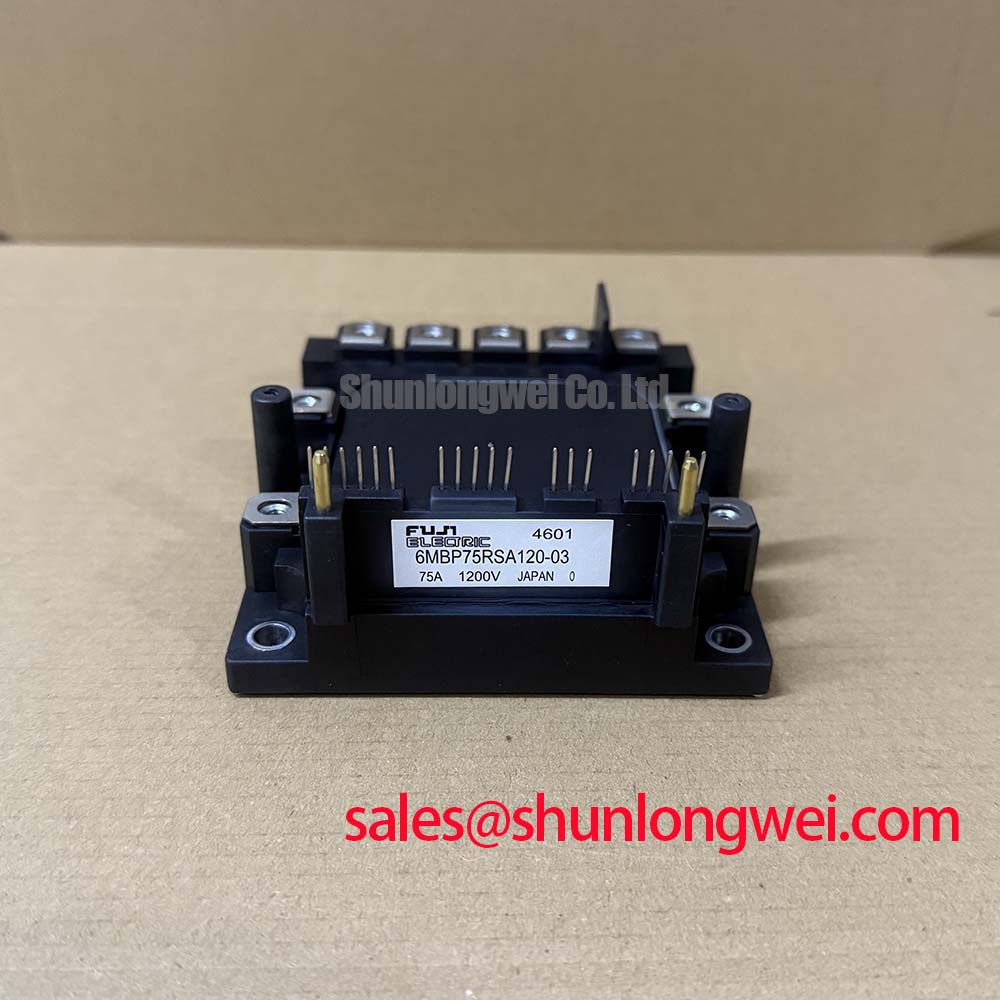
The confirmed product specifications are 1200 V rated voltage and 75 A rated current. These identify the electrical class of this Fuji Electric IPM, while the associated datasheet conditions remain essential to interpreting each rating. The package designation, Fuji Power Module, is not a dimensional drawing: terminal positions, connector orientation, mounting holes and heatsink contact geometry belong on the incoming inspection checklist.
For a cold electrical check, I first isolate the module from parallel circuit paths and identify the power terminals from its terminal diagram. In diode mode, compare the forward and reverse readings of corresponding power-terminal paths using the same meter, polarity and temperature conditions. The meter’s test current affects the displayed voltage, so a generic forward-drop window is not an acceptance specification for this module. An unusual reading calls for comparison with a documented reference and inspection of connected circuitry, rather than an immediate failure verdict.
💡 Bench Tip: Use ESD precautions and compare cold readings with a known-good reference under identical meter conditions before connecting the control harness.
Design Consideration: In a discrete IGBT circuit, separate turn-on and turn-off resistors can influence switching loss, current slew rate and ringing. That general technique must not be transferred automatically to this IPM. A resistor in a logic input or control-supply path is not an external gate resistor. Changing it can alter command timing or supply behavior without providing the intended control over the internal gate waveform.
Where an equipment-approved adjustment exists, evaluate its effect at the power terminals and control interface together. Observe the switching transition, phase-current behavior and fault output while keeping the test configuration repeatable. A quieter voltage trace alone does not establish a better operating point: slower transitions can increase switching dissipation. Conversely, faster transitions can increase overshoot and interference with adjacent control wiring. The permissible balance is a system validation result, not a resistance value inferred from the module’s current rating.
Replacement screening should also distinguish a related product from an interchangeable assembly. The 6MBP100RTB060 is a separate Fuji model for a comparison worksheet, not an automatic substitute for the 6MBP75VDA120-50. Compare the respective voltage classes, control interfaces, protection behavior, mechanical drawings and thermal conditions before considering a board-level change. A higher current designation alone does not resolve those differences.
For a commercial string inverter or micro-grid energy-storage converter, engineers evaluating this IPM should match the converter’s switching topology and control architecture to the module documentation. This is a compatibility assessment, not a claim that the part is a dedicated replacement for those systems. Procurement records should retain the full model suffix, drawing reference and equipment assembly reference so that an apparently similar module does not bypass the engineering review.
6MBP75VDA120-50 Operational Boundaries: Evaluating High dv/dt Cross-Conduction Shoot-Through Limits
Capture complementary command signals and the module’s fault indication on the same time reference when investigating suspected overlap. Start at the documented interface: controller outputs, signal returns, driver supplies and fault connections. A disturbance measured on the controller board does not by itself establish what occurred at the power semiconductor gate.
Design Consideration: Rapid collector-voltage changes can couple displacement current through an IGBT’s collector-to-gate capacitance. In a discrete implementation, the resulting gate disturbance depends on the off-state drive impedance and parasitic coupling. Active Miller clamps and negative gate bias are techniques used in suitable driver architectures, but they are not external modifications to prescribe for this IPM. Do not introduce a negative voltage at its logic terminals or infer an accessible clamp connection from a generic gate-driver schematic.
The useful integration question is whether the original control board maintains valid commands and stable supplies during commutation. Inspect signal-return routing, connector continuity and local decoupling against the equipment schematic. Keep sensitive control conductors separated from high-current switching paths where the assembly permits, while maintaining the equipment’s required electrical clearances. Any routing change should be checked for its effect on both interference pickup and return-current paths.
Dead time deserves a timing measurement rather than a guessed adjustment. Compare complementary commands at the receiving interface, accounting for propagation differences, controller startup behavior and fault recovery. Design Consideration: A suitable interlock prevents overlapping conduction commands under the system’s operating conditions; excessive blanking can also affect output behavior. The controller designer should determine the timing from documented module characteristics and measured system response, including behavior during enable and disable transitions.
Distinguish command overlap from a protection response before changing firmware. Record whether the fault indication precedes or follows the abnormal current event, whether a control supply moves outside its permitted range, and whether the event appears consistently on the same phase. Several mechanisms can produce similar equipment alarms. Comparing these traces helps separate an input disturbance, supply interruption and actual power-stage event without assigning a single cause from the alarm label.
Protection terminology also needs care. Desaturation detection uses collector-emitter behavior during conduction to identify a potentially abnormal condition; it is not the same measurement as a cold diode-mode check. Soft turn-off, where implemented by the relevant protection architecture, manages the interruption transient. Neither a specific desaturation threshold nor a short-circuit withstand interval should be attributed to the 6MBP75VDA120-50 without its manufacturer’s specification. Deliberately creating a short circuit is not an appropriate incoming inspection method.
The Precision Gate Drive Design reference provides background for interpreting drive-loop impedance, Miller coupling and protection timing. For this module, apply those principles through the documented IPM interface. A satisfactory acceptance record should preserve the observed command timing, control-supply behavior and fault response instead of treating a clean no-load waveform as proof of operation under load.
Preventing Spurious Faults: High-Frequency Commutation Loop Inductance Guidelines for 6MBP75VDA120-50
Inspect the complete commutation path between the local DC-link capacitor and module power terminals before blaming an intermittent fault on the module. Loose joints, displaced conductors or a changed capacitor connection can alter the transient seen at the power stage even when the control board is unchanged. Record the original conductor arrangement before dismantling a service assembly.
Design Consideration: Turn-off overshoot grows with the interaction between stray loop inductance and changing current. Reduce unnecessary loop area and keep outgoing and returning commutation paths closely coupled where the approved construction allows it. Overlapping planar conductors can help control inductance, but conductor spacing must also satisfy the equipment’s insulation and mechanical requirements. No universal inductance target follows from this module’s 1200 V rating.
Measure switching voltage with a probe arrangement appropriate to the voltage, common-mode behavior and measurement location. An unnecessarily long sensing loop can introduce apparent ringing. Compare repeatable traces using a consistent connection, then relate the measured peak to the actual DC-link condition and manufacturer limits. A trace captured at a remote capacitor terminal may not represent the transient at the module terminals.
Snubber selection should follow the observed transient and the surrounding circuit. Design Consideration: Capacitance, damping, pulse-current capability, dissipation and physical placement interact; adding capacitance without evaluating those factors can move stress elsewhere. The system engineer should establish the network from measured behavior and component ratings, then check its temperature and repetitive operating conditions. A snubber value cannot be selected responsibly from the IPM’s voltage and current labels alone.
Keep insulation verification separate from semiconductor blocking-voltage verification. The 1200 V rating is not permission to apply that voltage between arbitrary control pins, power terminals and the mounting surface. Use the manufacturer’s specified insulation test connections, conditions and limits when evaluating dielectric margin. Equipment-level clearance or withstand requirements must come from the applicable equipment documentation, rather than from an assumed property of the module housing.
Mechanical inspection should remain equally specific. Check the mounting surface, fastener arrangement and thermal interface against the package instructions. Do not infer a press-pack construction, calibrated disc-spring loading or double-sided cooling from the words “power module.” Mounting torque and interface preparation must correspond to the actual package and heatsink assembly; generic fastener guidance is not a Fuji specification for this part.
General background on wire bonding in semiconductor assembly helps explain why package construction matters, but it does not identify this model’s internal materials or establish its service life. Likewise, Powerex High Power Semiconductor Modules provides broader industry context, not a replacement qualification for this Fuji IPM.
After reassembly, compare the measured commutation transient with the pre-service record and inspect the terminal joints after the approved thermal test. If a fault persists, preserve the voltage trace, current trace, control-supply trace and fault timing together. Those observations give the repair engineer a concrete basis for investigating the module connection, bus structure or control interface without substituting a speculative diagnosis for measured evidence.