Content last revised on September 10, 2026
7MBP50RTB060: 600V 50A 7-in-1 IGBT PIM for High-Efficiency Motor Drives
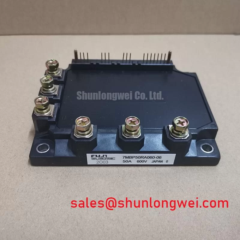
The 7MBP50RTB060 is a compact 7-in-1 IGBT module engineered to reduce conduction losses and simplify the design of low-power motor control systems. Featuring core specifications of 600V, 50A (Inverter), and a typical VCE(sat) of 2.0V, this Power Integrated Module (PIM) delivers enhanced energy efficiency and an accelerated design cycle. The module's all-in-one design, integrating rectifier, brake, and inverter stages, directly addresses the need for compact and cost-effective Variable Frequency Drive (VFD) solutions. For 240V AC motor drives up to 7.5kW requiring a balance of efficiency and high integration, the 7MBP50RTB060 provides an optimized power stage solution.
Key Parameter Overview
A Specification Breakdown Focused on Conduction Losses and Thermal Integrity
The technical specifications of the 7MBP50RTB060 are tailored for performance and reliability in demanding power conversion applications. The table below highlights the critical parameters that directly influence system efficiency and thermal stability.
| Parameter | Symbol | Condition | Value | Engineering Implication |
|---|---|---|---|---|
| Collector-Emitter Voltage | Vces | - | 600V | Provides a safe operating margin for applications running on 200-240V AC lines. |
| Continuous Collector Current (Inverter) | Ic | Tc=80°C | 50A | Defines the module's capacity for continuous motor load operation. |
| Collector-Emitter Saturation Voltage (Inverter) | VCE(sat) | Ic=50A, Vge=15V | 2.0V (typ), 2.7V (max) | A low typical value directly translates to lower conduction losses, improving overall system efficiency and reducing heat generation. |
| Forward Voltage (FWD) | Vf | Ie=50A, Vge=0V | 2.0V (typ), 2.5V (max) | Indicates low losses in the freewheeling diode, critical for PWM motor control. |
| Isolation Voltage | Viso | AC, 1 minute | 2500V | Ensures robust electrical isolation between the power circuit and the control logic, meeting safety standards. |
| Operating Junction Temperature | Tj | - | +150°C | Specifies the maximum allowable temperature for the semiconductor junctions. |
Download the 7MBP50RTB060 datasheet for detailed specifications and performance curves.
Application Scenarios & Value
System-Level Advantages in Compact AC Motor Control and Servo Systems
For an engineer developing a compact VFD for a conveyor belt system, where enclosure space is limited and energy efficiency is critical, the 7MBP50RTB060 offers a decisive advantage. Its 7-in-1 Power Integrated Module (PIM) architecture integrates the input rectifier, brake chopper, and output inverter, eliminating the need for multiple discrete components and drastically reducing the required PCB footprint. This high level of integration not only saves space but also simplifies assembly and can reduce system-level electromagnetic interference (EMI). The low VCE(sat) of 2.0V is a key performance metric that directly minimizes heat dissipation during operation, enabling the use of a smaller heatsink and facilitating a more compact, fan-less, or passively cooled final product design.
This module is ideally suited for a range of motion control systems, including:
- General-purpose inverters up to 7.5kW
- AC servo drives and robotics
- Small industrial pumps and fans
- HVAC motor controllers
While the 7MBP50RTB060 is optimized for 600V systems, for applications requiring operation on 400/480V AC lines, a 1200V-class module like the 7MBR50VP120-50 offers the necessary voltage headroom.
Technical Deep Dive
Analyzing the Role of VCE(sat) and Integrated Thermistor in System Reliability
Two often-overlooked features that significantly contribute to the long-term reliability of a system using the 7MBP50RTB060 are its low saturation voltage and the integrated thermistor. The VCE(sat) can be understood as the electrical "friction" the IGBT presents when it's switched on. A lower value, like the 2.0V typical for this module, means less power is converted into waste heat for the same amount of current. This reduction in power loss (P_loss = VCE(sat) x Ic) is fundamental to efficient Thermal Management, directly lowering the junction temperature and reducing stress on the entire component.
Complementing this efficiency is the integrated NTC thermistor. This component acts as a built-in fever thermometer for the module, providing the control system with a direct, real-time measurement of the substrate temperature. This enables the implementation of a precise thermal feedback loop. Instead of relying on less accurate external heatsink sensors, a gate driver or microcontroller can monitor the thermistor to proactively derate the output current or trigger a safe shutdown if the module approaches its thermal limits. This intelligent protection scheme is crucial for preventing catastrophic failures and extending the operational life of both the module and the end equipment.
Frequently Asked Questions
Engineering Questions on Implementation and Performance
What is the primary advantage of the 7-in-1 topology in the 7MBP50RTB060?
Its main benefit is design simplification and space savings. By integrating the input three-phase rectifier, brake chopper, and output three-phase inverter into a single, compact package, it reduces the bill of materials (BOM), minimizes PCB layout complexity, and shortens power interconnections, which can help mitigate EMI.
How does the low VCE(sat) of 2.0V impact the thermal design?
A lower collector-emitter saturation voltage directly reduces conduction power loss, a primary source of heat in an IGBT Module. This reduction in generated heat allows engineers to specify smaller, lighter, and lower-cost heatsinks, thereby improving the power density and overall cost-effectiveness of the final system.
How should the integrated NTC thermistor be utilized in a design?
The thermistor should be connected to an analog-to-digital converter (ADC) input on the system's microcontroller. By referencing the resistance-temperature (R-T) curve provided in the official datasheet, the control firmware can accurately translate the measured resistance into a temperature reading. This data should be used to implement over-temperature protection (OTP) logic, triggering alerts, power derating, or a complete shutdown when the module's temperature exceeds predefined safe operating limits.
For detailed technical inquiries or to assess the suitability of the 7MBP50RTB060 for your specific design, please contact our engineering support team for assistance.