Content last revised on October 5, 2026
Transient Dynamics and Electrical Design for 7MBR15SC120
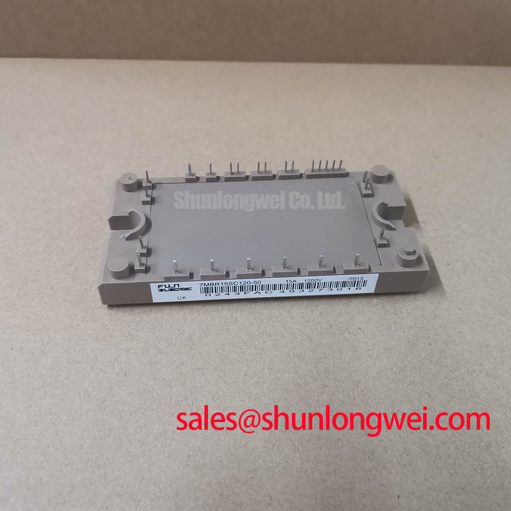
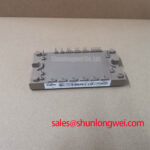
The Fuji Electric 7MBR15SC120 is a power module in the P609 (M629) package. Its collector to emitter voltage rating is 1200 V and its collector current rating is 15 A, both Official Specification values. The typical collector to emitter saturation voltage is 2.3 V; the typical diode forward voltage is 2.1 V. These typical values describe conduction behavior at the manufacturer's specified test conditions, not guaranteed voltage drops throughout an operating cycle.
For a drive that trips during acceleration or repeated positioning moves, separate conduction heating from switching heating before judging the module. A current trace, gate command and case temperature trend are more useful together than a single cold resistance reading. Switching loss depends on the actual bus voltage, current, gate drive and switching frequency. Those system conditions must be checked against the original Fuji Electric documentation and the drive design; the headline current rating alone does not establish a permissible pulse train.
Design Consideration: A junction temperature estimate during a short overload requires the applicable transient thermal impedance data, the pulse history and a defensible loss estimate. Where the required thermal curve or switching loss data are unavailable, do not assign a numerical peak junction temperature or claim a calculated thermal margin. Instead, capture the operating waveform, inspect cooling contact and compare the observed case temperature with a known working installation under comparable duty. The Advanced Thermal Management Revolution provides broader thermal interface context; it does not replace module specific limits.
Before changing a gate resistor or adding an active clamp, check the existing driver schematic and measure the switching waveform with suitable isolated instrumentation. Miller coupling can contribute to unintended gate movement during a fast voltage transition, but the remedy depends on the installed driver, wiring and measured behavior. The Fuji Electric Power Semiconductors Portal is a manufacturer reference for locating relevant module documentation.
Field Diagnostics and Commissioning in Drive Topologies
When a repaired drive will not enable, begin at the equipment fault log and work outward: confirm DC link condition, inspect the module terminals and surrounding bus connections, then compare the gate drive supply and commands with the service documentation. Repeat the cold terminal checks with the module disconnected as the equipment procedure requires. A mismatch may indicate a module fault, a parallel circuit path or a measurement setup difference; it is not, by itself, a diagnosis.
During controlled commissioning, observe collector to emitter voltage at turn off and check it against the 1200 V Official Specification rating. Design Consideration: Short, well routed power connections and appropriately positioned DC link or snubber components can help limit inductive overshoot. Their placement and values must follow the equipment layout and switching test results rather than a generic parasitic inductance target. Check probing technique first if an apparent spike changes substantially with the measurement lead arrangement.
If the drive has a rectifier or another module on the same DC link, identify its function from the actual circuit diagram before ordering parts. The 7MBR15NE120-01 can be examined as a separate module listing during that circuit review; its presence here does not establish electrical or mechanical interchangeability with the 7MBR15SC120. Rectifier conduction behavior and mains harmonics belong to the complete input stage, so they cannot be inferred from this module's ratings.
Altitude and radiation related failure mechanisms warrant application level review where the equipment specification calls for it. No module specific FIT rate, single event burnout rate or altitude derating figure is established by the ratings stated here. Design Consideration: For an elevated site, the equipment engineer should obtain applicable manufacturer reliability guidance and assess the measured DC link voltage and transient headroom before declaring the installation suitable.
Assembly Integrity and Overvoltage Trip Checks
Before attributing a deceleration trip to the 7MBR15SC120, inspect the braking path shown on the drive schematic. Check whether the controller commanded braking, whether the associated switching device responds and whether the resistor circuit is intact. A rising DC link during motor deceleration can reflect returned energy, but the cause of a trip must be established from measured bus behavior and the equipment's protection sequence.
Engineering Recommendation: Size or replace a braking device and resistor only against the original equipment requirements and measured duty. This module's 1200 V and 15 A ratings do not specify a braking resistor value, an allowable deceleration energy or the existence of an internal braking switch. Likewise, a gate driver optocoupler or digital isolator should be assessed against the actual common mode switching waveform and its own documented limits, rather than assigned a CMTI requirement from the module name.
For a precision stepper or BLDC servo motion actuator, first compare the removed assembly's circuit position, terminal layout and mechanical envelope. The FP10R12KE3 is a separate listing worth including in a documented cross model comparison, not a drop in substitute on the basis of voltage class. Verify topology, pin assignments, gate drive, thermal interface and protection behavior before considering any change. Fuji Electric Europe Semiconductor & Power Electronics is another manufacturer channel for documentation needed in that review.
7MBR15SC120 Thermal Contact and Mounting Checks
Inspect the mounting surface and the P609 (M629) package seating before reconnecting power terminals. Remove old interface material according to the equipment maintenance procedure, check for debris or raised edges, and look for uneven contact marks on the removed assembly. A thick deposit of thermal compound is not a substitute for a flat, correctly seated interface. Any interface material and application method should be compatible with the original mechanical design.
⚠️ Field Alert: Do not choose screw torque from the package name; follow the documented fastener and equipment mounting specification.
Tighten mounting fasteners in the sequence specified for the assembly, then confirm that the module remains seated without visible rocking or cable strain. If the drive previously tripped only after warming, log case temperature at a repeatable operating point and compare it with the pre-repair record or a comparable working unit. That check may reveal a contact or cooling concern, but it cannot isolate junction temperature without the relevant thermal data. Finish by rechecking terminal security and repeating the controlled switching and protection tests required by the equipment service procedure.