

Content last revised on October 7, 2026
DC Bus Headroom and Incoming Electrical Checks for APT2X101D100J
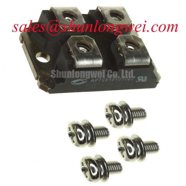
Check the cold terminal map of APT2X101D100J against the original equipment schematic before connecting a meter or fitting the module to a heatsink. The supplied product record identifies Microsemi, a 95.0 A current rating and an SP4 / SP6 module package designation. These are the available Official Specifications for this listing. “Standard Industrial Rating” does not state a voltage limit; the exact voltage rating, terminal functions and mechanical variant must be confirmed from the applicable manufacturer documentation before electrical testing or installation.
Start with the equipment’s bus-voltage record and the module’s confirmed voltage rating, not the wording “standard industrial.” For an inverter welder or a medium-frequency induction-heating supply, the relevant comparison is the highest bus voltage observed during operation against the device’s permitted blocking voltage, including switching transients. This is a Design Consideration, and the allowable margin must be established by the system engineer once the exact device specification is available.
At the incoming bench, record the terminal markings and compare each identified conduction path with a known-good unit using the meter’s diode function. Reverse the probes to check the opposite polarity, and compare readings only under the same meter setting and component temperature. A diode-mode result can reveal a gross short or an unexpected open path, but it cannot establish the device’s full blocking-voltage capability. Do not infer an IGBT gate, an auxiliary emitter or a particular internal diode arrangement from the catalog category alone; those features require a confirmed pinout.
💡 Bench Tip: Keep the module disconnected from the equipment and discharge the DC bus before any cold terminal comparison.
Design Consideration: Equipment operating at elevated altitude may need a separate assessment of cooling, insulation coordination and voltage stress. No device-specific altitude derating, terrestrial-neutron single-event-burnout rate or failure-in-time value is established by the supplied product data. A quantitative reliability claim would require applicable manufacturer evidence and defined operating conditions; ordinary incoming measurements cannot provide it.
Thermal Contact and Switching-Loop Inspection
The SP4 / SP6 module designation is useful when locating mounting information, but it is not a dimensional drawing or a tightening instruction. Before assembly, compare the received base and terminal positions with the equipment drawing. Inspect the heatsink contact area for debris, raised edges and uneven seating. Where the approved assembly uses thermal interface material, apply and inspect it according to the equipment or material specification rather than assigning this part an unverified coating thickness or screw torque.
Design Consideration: Uniform contact helps avoid concentrated thermal resistance. Tighten the fasteners in the sequence specified for the approved mounting arrangement, then check that the module sits evenly without forcing its terminals into alignment. If a previously installed unit shows an uneven contact imprint, investigate the heatsink surface, mounting hardware and assembly method together; the imprint alone does not identify a device fault.
Inspect the nearby DC-link conductors and any snubber connection while the assembly is accessible. A compact switching loop can help limit inductive voltage overshoot, but there is no justified inductance target for this listing. Designers should establish placement and clearances from the actual circuit, operating voltage and insulation requirements, then verify peak voltage at the device during controlled switching tests. A CM50DY-28H module may appear elsewhere in equipment-level power-stage assessments; its role and compatibility must be checked against the circuit rather than presumed from proximity in a parts list.
Terminal Routing and Waveform Diagnosis
Trace each module terminal from the approved pinout to the equipment schematic before evaluating a driver waveform. If the confirmed device has a gate-drive connection, inspect its drive and return routing separately from the high-current path. If it does not, gate-source or Kelvin-emitter advice is inapplicable to this part. This distinction prevents a catalog classification from becoming an incorrect test procedure.
For an intermittent power-stage fault, capture the relevant device voltage and current waveforms with appropriately rated instruments and compare them with a documented healthy operating state. Ringing or an unexpected peak calls for examination of bus connections, snubber condition, probe placement and the associated drive circuit where one exists. None of those observations, on its own, proves that the module is defective. Maintain the equipment’s specified clearance and creepage arrangements when moving conductors or replacing nearby hardware; a universal layout-clearance number cannot be assigned without the system’s insulation design.
A replacement assessment should begin with terminal functions, voltage rating, current test conditions, package drawing, mounting interface and thermal data. The MBM200H45E2-H can be reviewed as a separate candidate in a broader hardware comparison, but the supplied information does not establish it as a direct substitute for APT2X101D100J.
Pulsed Loading, Thermal Evidence and Release to Assembly
The stated 95.0 A current rating is an Official Specification in the supplied record, not a complete pulsed-load limit. To assess overload in a welder or induction-heating supply, the engineer needs the manufacturer’s rating conditions and transient thermal data alongside the equipment’s measured current waveform, pulse duration, repetition pattern and case temperature. Without a validated transient thermal model, a numerical peak-junction-temperature margin would be an unsupported calculation.
For incoming QA, retain the cold terminal readings, package observations and the drawing revision used for the pinout check. For an installed module, compare case-temperature measurements and operating waveforms at repeatable load conditions before attributing a thermal alarm to the semiconductor. The Ultimate IGBT Knowledge Base provides background on power-stage terminology, but any lifetime estimate still needs device-specific evidence. The Arrhenius equation describes a temperature-dependent rate model; it does not, by itself, predict this module’s service life. Hold assembly approval until the exact voltage rating, pinout and mounting instructions have been matched to the equipment documentation.