Content last revised on October 21, 2026
Preventing Spurious Faults: High Altitude Cosmic Ray Induced SEB Failure Guidelines for BSM200GA170DLC
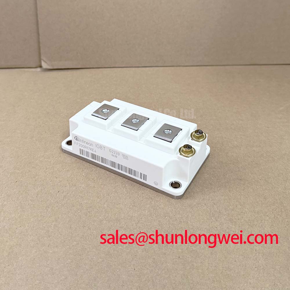
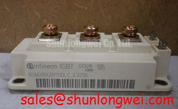
When a wind turbine converter shows an intermittent high voltage shutdown after installation at elevation, record the DC link voltage, switching state, ambient conditions, and fault timestamp before replacing the power module. The BSM200GA170DLC is an Infineon IGBT module with an official rated voltage of 1700.0 V, an official rated current of 200.0 A, and a Module package.
High-altitude operation changes the environmental context for insulation coordination and increases the engineering attention given to terrestrial neutron exposure. A single-event burnout assessment requires the actual device technology data, converter operating voltage profile, exposure location, switching duty, and an authoritative neutron or SEB model. FIT values and altitude derating percentages should not be inferred from the voltage marking alone. The practical task is to establish DC-bus headroom through controlled voltage and switching tests while recording transient peaks at the module terminals.
As a Design Consideration, keep the high-energy commutation path compact, maintain consistent creepage and clearance around the DC link, and prevent contamination or condensation from reducing the effective insulation path. At installations above 2000 m, the system engineer should review the applicable insulation coordination standard, enclosure pressure and humidity behavior, and the measured electrical field distribution. The Precision Gate Drive Design reference can support gate-loop review and transient measurement planning.
The freewheel diode response also deserves attention during high-altitude fault analysis. Reverse-recovery softness factor S is not an official parameter supplied here for this model, so engineers should evaluate reverse-recovery current, voltage overshoot, and radiated EMI using the actual converter commutation waveform. Gate-trigger terminology such as IGT and VGT belongs to thyristor evaluation and should not be transferred to this IGBT module without a verified topology and datasheet basis.
Preventing Spurious Faults: Type 2 Coordination for Protecting IGBT Modules
Type 2 coordination starts with matching the semiconductor fuse clearing behavior to the module’s short-circuit and transient withstand capability, rather than selecting a fuse from nominal current alone. The protection study should compare total clearing I²t, prospective DC-link fault energy, fuse response time, and the module’s documented short-circuit limits under the intended gate-drive conditions.
For the DC-link layout, minimize parasitic busbar inductance in the commutation loop to suppress turn-off overshoot. The supplied engineering brief identifies a target of 25 nH or less as a design objective, not as an official BSM200GA170DLC specification. The final value must be verified from the assembled busbar with suitable high-bandwidth probing. Film snubber capacitors should be positioned according to the actual current loop so that the measurement captures the module terminals rather than a convenient but electrically remote point.
When the rectifier and inverter sections are reviewed together, the FF200R12MT4 may be evaluated as a related front-end device in systems where its electrical ratings and topology are appropriate. This is a neutral system-level comparison, not a substitute recommendation. Confirm fuse coordination, gate-driver interlock behavior, and protection timing across the complete converter.
| Item | BSM200GA170DLC | BSM150GB170DN2 |
|---|---|---|
| Manufacturer | Infineon | Infineon |
| Rated voltage | 1700.0 V, Official Specification | Consult applicable datasheet |
| Rated current | 200.0 A, Official Specification | Consult applicable datasheet |
| Package | Module, Official Specification | Consult applicable datasheet |
The BSM150GB170DN2 can be included in a cross-reference review when the original equipment documentation permits a different current class. Mechanical footprint, gate characteristics, diode behavior, thermal interface, and protection settings must be checked before any substitution is considered.
BSM200GA170DLC Operational Boundaries: Preventing Ceramic Substrate Rupture During Installation
Inspect the copper baseplate and heatsink contact surfaces for bowing, burrs, embedded debris, or localized high spots before applying thermal interface material. Uneven contact can concentrate mechanical stress in the ceramic substrate and produce thermal resistance variation across the mounting area.
For this installation, a thin and continuous TIM layer is a Design Consideration; the supplied engineering target is approximately 50–80 µm, subject to the selected compound and surface condition. Apply the material uniformly, seat the module without sliding it across the heatsink, and tighten fasteners progressively in a diagonal cross-pattern using a calibrated tool. The correct torque is determined by the module mechanical documentation, fastener specification, and heatsink interface design rather than by current rating.
After assembly, check that the heatsink remains seated without rocking and compare thermal behavior between equivalent phases during a controlled operating test. A rising case temperature imbalance may reflect TIM distribution, airflow, electrical loading, or sensor placement, so investigate the complete thermal path rather than assigning a single cause.
⚠️ Maintenance Note: Clean the heatsink and inspect TIM condition during scheduled service while monitoring contact temperature and verifying that the cooling-air path remains unobstructed.
Assembly Integrity and Layout Architecture: Baseplate Isolation Breakdown Testing
Isolation testing should be performed with the module disconnected from the gate driver, sensing circuits, capacitors, and other equipment that could be exposed to the test voltage. If the assembly procedure specifies testing at 2.5 kV DC with a minimum resistance of 500 MΩ, treat those values as an inspection criterion for that procedure and follow the applicable equipment safety rules.
Record the terminal grouping, test duration, ambient humidity, surface cleanliness, and measured result. If the reading changes materially after cleaning or drying, investigate airborne dust, condensation, flux residue, and creepage contamination before removing the module from service. Do not touch or reconnect the circuit until the tester has discharged the assembly and the absence of stored energy has been confirmed.
Review the PCB and busbar arrangement for adequate terminal-to-baseplate clearance and a clean creepage path around the module. In wind converter cabinets, salt or industrial dust can combine with moisture and create a conductive film, particularly near cable lugs and shield terminations. The enclosure sealing strategy, heater or dehumidification controls, and maintenance interval should be selected by the system designer after reviewing the actual site environment.
For broader power-device context, engineers may consult Infineon’s Infineon EasyPACK™ information and the Infineon OptiMOS™ and CoolMOS™ Power MOSFETs portfolio when comparing semiconductor technologies, while keeping the BSM200GA170DLC’s verified product identity and application limits separate from those families.