Content last revised on May 19, 2026
CM100TL-24NF Mitsubishi 1200V 100A NF-Series IGBT Module with Integrated Brake Chopper
Engineering Snapshot
Compact 7-Element Power Stage Engineered for Thermal Stability
How do you fit a complete three-phase inverter plus dynamic brake into a single, heat-tolerant module for a 22 kW AC drive? The CM100TL-24NF from Mitsubishi Electric answers that question with a 1200V / 100A seven-element configuration on an isolated AlN-grade DBC substrate. Key takeaways: low VCE(sat) ≈ 2.7 V, integrated brake leg, and an NF-series isolated baseplate simplifying heatsink mounting. For 380–480 V industrial drives needing brake capability without external chopper hardware, this module is the optimal fit.
Frequently Asked Questions
Critical Pre-Design Questions on Topology and Thermal Behavior
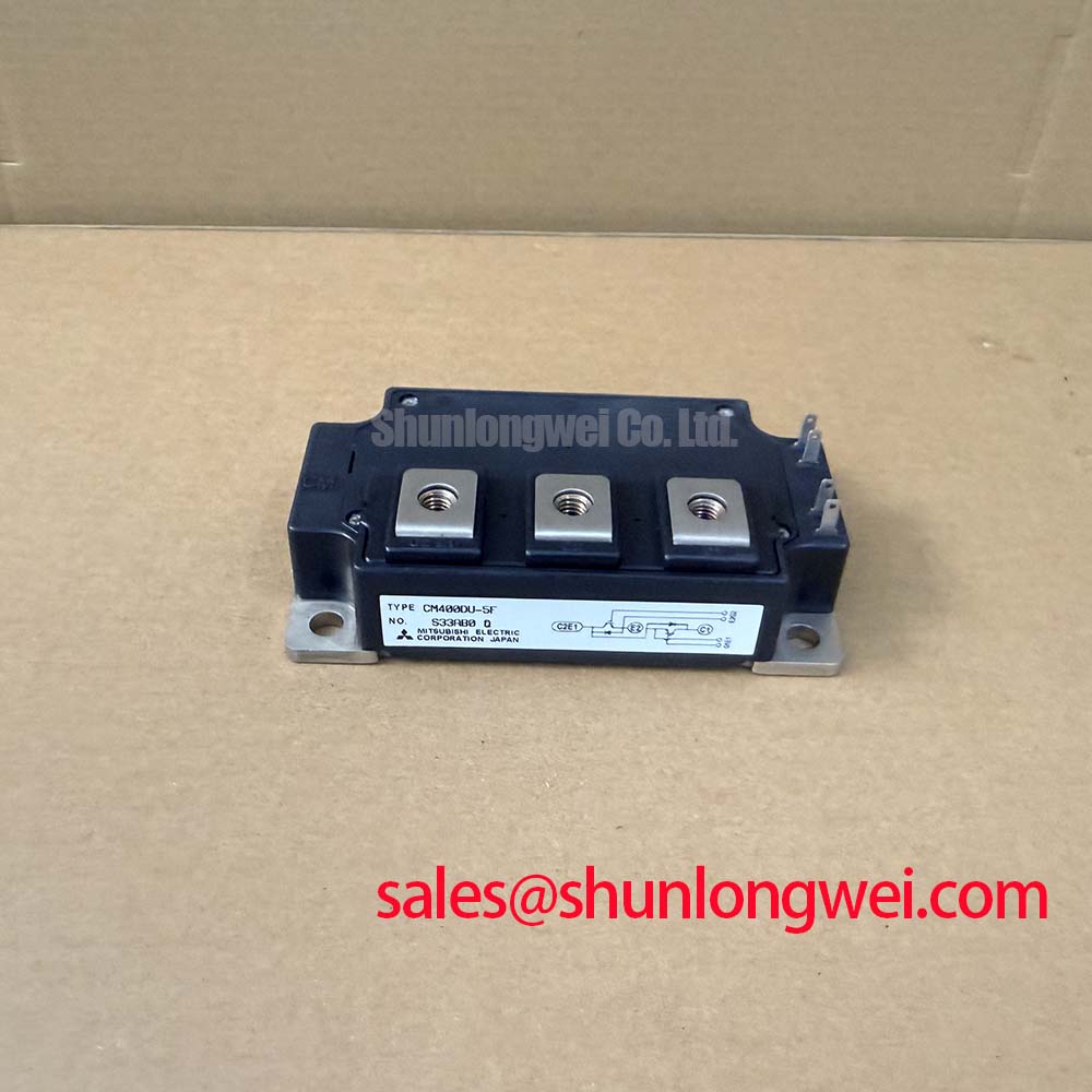
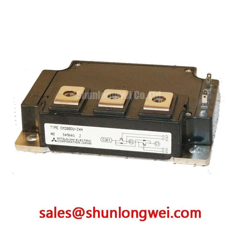
What is the configuration of the CM100TL-24NF? It integrates a 3-phase IGBT inverter bridge (six switches with anti-parallel diodes) plus an additional IGBT/diode pair for dynamic braking, forming a 7-element power stage in one NF housing.
What dictates the 100 A rating in continuous service? The 100 A IC rating is specified at Tc = 25 °C. In real drive cabinets, derate using the junction-to-case thermal resistance and ambient/heatsink rise; usable continuous current is typically 60–70 A at Tc = 80 °C.
Key Parameter Overview
Specs Interpreted Through a Thermal Reliability Lens
| Parameter | Value | Engineering Value |
|---|---|---|
| VCES | 1200 V | Headroom for 380–480 VAC mains with surge margin |
| IC (continuous) | 100 A | Supports up to ~22 kW drive ratings |
| ICM (peak) | 200 A | Handles motor starting and overload pulses |
| VCE(sat) typ. | 2.7 V @ 100 A | Lower conduction loss, cooler operation |
| Configuration | 7-element (3-phase inverter + brake) | Integrated brake leg removes external chopper module |
| VGES | ±20 V | Standard gate-drive compatibility |
| Isolation | 2500 Vrms / 1 min | Direct mounting to grounded heatsink |
| Tj (max) | 150 °C | Margin for transient overload events |
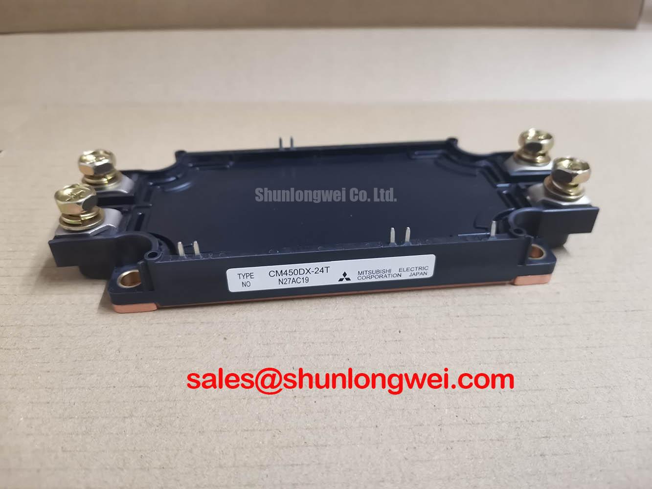
| Package | NF-series, isolated baseplate | Compact footprint, simplified assembly |
Download the CM100TL-24NF datasheet for detailed specifications and performance curves: CM100TL-24NF datasheet.
Technical Deep Dive
How the Integrated 7-Pack Topology Improves Reliability and Density
Conventional 22 kW drives often combine a discrete 6-pack inverter with a separate chopper IGBT and external rectifier circuitry. The CM100TL-24NF consolidates the inverter switches and brake chopper inside a single isolated package, cutting interconnect inductance and bus-bar complexity. Think of it like swapping a wiring harness for a printed bus plate — fewer joints, fewer failure modes.
The NF baseplate uses a high-conductivity ceramic substrate that maintains a uniform thermal path under power cycling. This directly improves power cycling capability, a major concern for drives starting heavy loads several times per hour. Combined with a tight VCE(sat) distribution across all seven switches, designers achieve balanced junction temperatures across the inverter bridge — critical for predictable life expectancy. For deeper context, see this practical reference on why Rth matters in IGBT thermal performance.
Application Scenarios & Value
From Conveyor Drives to Crane Hoists — Where Brake Integration Pays Off
Engineers often face a recurring problem in vertical-axis applications: regenerative energy from a descending crane load or decelerating conveyor must be dissipated before the DC-link capacitors over-volt. With the CM100TL-24NF, the integrated brake IGBT switches a resistor directly off the DC bus, bypassing the need for a separate chopper module. In a 15 kW hoist drive, this removes one component, one set of gate-drive channels, and one heatsink interface — shrinking enclosure depth by roughly 20%.
Typical deployments include:
- General-purpose AC drives (11–22 kW) compliant with IEC 61800-3 EMC classes
- Servo amplifiers for machine tools requiring rapid deceleration
- Elevator and hoist drives where dynamic braking is mandatory
- Industrial UPS in-line inverter stages up to ~15 kVA
- Pump and fan VFDs with safety-critical stop functions
For systems requiring higher continuous current within the same NF family, the related CM150TL-24NF offers a 150 A rating with identical topology. If the design does not need an integrated brake leg, the dual-switch CM100DY-24NF provides a half-bridge configuration in the same NF package family. Engineers evaluating broader trade-offs can also consult this guide on IGBTs in high-efficiency inverter AC systems.
Additional Engineering FAQ
Field-Level Questions on Drive and Gate-Drive Implementation
Why use a 1200V class part on a 480 VAC line? The peak DC-bus voltage at 480 VAC nominal can exceed 800 V during regenerative events. The 1200V VCES rating leaves headroom above transient overshoots caused by stray inductance.
How does VCE(sat) ≈ 2.7 V influence cooling design? At 100 A, conduction loss is roughly 270 W per active switch at full load. Combined with switching losses, an NF heatsink delivering Rth(s-a) ≤ 0.05 °C/W is typical for sustained operation.
Is a negative gate voltage required? Mitsubishi recommends −5 to −10 V off-state bias under hard-switched high-dv/dt conditions to prevent parasitic turn-on, especially in the brake-chopper switch.
Can the brake IGBT operate continuously? No. The brake circuit is rated for intermittent duty matched to the brake resistor's thermal time constant; continuous chopping above 50% duty risks Tj exceedance.
What gate resistor range is appropriate? Typical RG values of 4.7 Ω–10 Ω balance switching loss and dv/dt control; final selection depends on bus inductance and EMI targets.
Engineer's Closing View
For drive designers consolidating inverter, freewheel, and brake functions into a single 22 kW-class power stage, the CM100TL-24NF offers a fact-based path to reduced part count and tighter thermal control. Verify availability and revision-level dating before locking your BOM, and review the official Mitsubishi IGBT module portfolio alongside the datasheet to confirm fit for your specific load profile.