
Content last revised on September 10, 2026
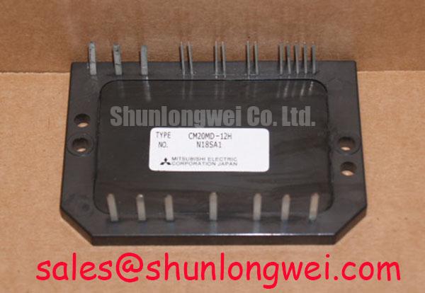
CM20MD1-12H Mitsubishi IGBT Module: Streamlining Compact Drive Engineering with Integrated 600V 20A CIB Architecture
The Mitsubishi CM20MD1-12H consolidates a 3-phase rectifier converter and 3-phase IGBT inverter into a single insulated package to minimize system layout footprint. For 400V AC input compact motor drives requiring minimal footprint, this 600V 20A module provides an optimal integrated power stage.
Top Specifications: 600V VCES | 20A IC | 2500V AC Viso
- Consolidates converter and inverter power stages into one chassis.
- Features fast-recovery free-wheel diodes for high-frequency switching up to 25 kHz.
How does an integrated Converter-Inverter module simplify thermal management? By isolating all semiconductor dies on a single aluminum baseplate, thermal dissipation is routed efficiently through a unified heatsink interface.
Key Parameter Overview
Grouped Electrical and Thermal Specifications for Integrated Stage Evaluation
The technical parameters of the CM20MD1-12H reflect its dual-stage converter-inverter configuration, designed for direct mounting to cooling assemblies in space-constrained industrial systems.
| Functional Stage | Parameter Symbol | Specification Rating | Engineering Significance |
|---|---|---|---|
| Inverter Section | VCES | 600V | Maximum collector-emitter voltage rating for 200V–400V AC line drive applications. |
| Inverter Section | IC | 20A DC (Tc = 80°C) | Continuous collector current capacity per arm during standard operation. |
| Inverter Section | VCE(sat) | 2.0V typ / 2.8V max | Low saturation voltage minimizing steady-state conduction thermal losses. |
| Converter Section | VRRM | 800V | Repetitive peak reverse voltage for the 3-phase input diode bridge. |
| Converter Section | IO | 20A 3-phase DC output | Rectified DC output capability supplying the internal inverter bus. |
| Thermal / Isolation | Viso | 2500V AC 1 min | Baseplate electrical isolation rating ensuring compliance with safety standards. |
| Thermal / Isolation | Rth(j-c) | 1.5°C/W max (IGBT die) | Junction-to-case thermal resistance per IGBT switch for cooling sizing. |
Download the CM20MD1-12H datasheet for detailed specifications and performance curves.
Application Scenarios & Value
Optimizing Compact Industrial Drives and Motion Control Systems
Engineers designing compact Variable Frequency Drives (VFDs), conveyor controls, and industrial robotics frequently encounter strict enclosure volume restrictions. In traditional discrete designs, wiring a standalone three-phase diode bridge rectifier to a six-pack IGBT bridge consumes substantial printed circuit board area while introducing parasitic interconnect inductance.
The CM20MD1-12H resolves these physical layout bottlenecks by integrating the input AC-to-DC conversion bridge and the DC-to-AC output inverter stage into a single insulated baseplate module. The 600V voltage ceiling and continuous 20A current rating accommodate standard low-power AC motor drives. The discrete super-fast recovery free-wheel diodes (70ns recovery speed) allow high-frequency PWM switching between 20 kHz and 25 kHz, keeping acoustic motor noise to a minimum in automation environments.
What is the primary benefit of the CM20MD1-12H integrated CIB architecture? It reduces total PCB footprint by unifying rectifier and inverter stages. For drive designs that demand substantially higher current output under a similar voltage rating, engineers may evaluate higher-capacity alternatives like the CM150DY-12H. Exploring an IPM vs discrete IGBT design guide provides further strategic context on module integration trade-offs.
Technical & Design Deep Dive
Inside the Converter-Inverter Integrated Packaging Strategy
To evaluate the system-level advantages of the CM20MD1-12H, power engineers must examine how integrated packaging alters thermal pathways and conduction dynamics. The module incorporates six IGBT switches with anti-parallel diodes alongside six rectifier diodes on a thermally conductive ceramic substrate bonded to an aluminum baseplate.
The VCE(sat) rating of 2.0V typical plays a key role in reducing active thermal dissipation. Think of VCE(sat) conduction loss like pipe resistance in a fluid pumping system; lower saturation voltage acts like a smoother, wider pipe, drastically cutting heat generated per amp of current passing through the junction.
Furthermore, consolidating the 3-phase converter diode bridge and 3-phase inverter in a single housing is like combining a vehicle's engine block and transmission into a single cast casing. This integration eliminates inter-stage busbars, minimizes stray loop inductance between the DC-bus capacitor and switches, and ensures uniform thermal expansion across all power components mounted on a single heatsink surface.
For more background on voltage-controlled semiconductor principles, reference our technical articles on how an IGBT works and decoding IGBT datasheets.
Frequently Asked Questions
Addressing Core Engineering and Integration Queries
How does the integrated Converter-Inverter topology of the CM20MD1-12H benefit system layout?
By integrating the 3-phase input rectifier bridge and 3-phase inverter bridge into one package, the CM20MD1-12H eliminates external interconnect wires between power stages. This simplifies PCB trace routing, reduces parasitic loop inductance, and reduces the overall physical enclosure footprint.
What insulation rating does the baseplate offer for safety compliance?
The module features an isolated aluminum baseplate rated for an isolation voltage (Viso) of 2500V AC for 1 minute. This allows direct thermal mounting onto a grounded metallic heatsink without requiring extra external ceramic insulation pads.
What gate drive parameters should be maintained for 20 kHz PWM operation?
To achieve fast switching transitions without excessive dv/dt noise, a standard gate voltage of +15V is recommended for turn-on, paired with an appropriate gate resistor (RG around 31Ω). Designers should ensure low-inductance driver traces to prevent spurious gate ringing during rapid switching events.
Engineers evaluating the CM20MD1-12H for compact motor drive or automation platforms can consult technical datasheets or submit inquiries to verify thermal and mounting compatibility for their target design budget.