

Content last revised on October 3, 2026
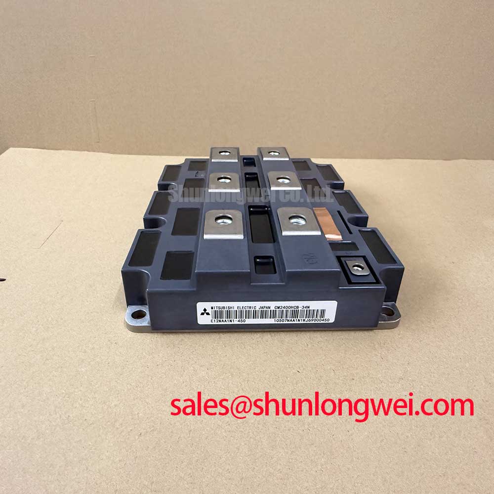
CM2400HC-34N Thermal-Electrical Optimization: Baseplate Thermal Grease Layer Control Practical Tuning
| Model | CM2400HC-34N |
|---|---|
| Manufacturer | Mitsubishi Electric |
| Product category and package | IGBT module; module package |
| Rated voltage | 1700 V (Official Specification) |
| Rated current | 2400 A (Official Specification) |
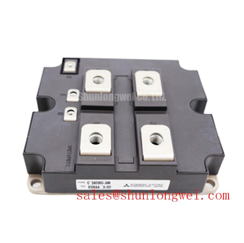
Check the cold collector-to-emitter path and gate-to-emitter isolation before mounting the CM2400HC-34N, using the equipment schematic to identify the correct terminals. Record the meter polarity and reading for comparison with a known-good unit under the same test conditions. A diode-mode reading alone does not establish the module’s full switching condition, but an unexpected low-impedance path is a reason to stop the installation and investigate.
Inspect the baseplate and cooler contact surfaces for debris, raised edges, and old thermal compound. As a Design Consideration, apply a continuous, controlled thermal interface layer rather than assuming that more grease improves cooling. An excessively thick layer can add thermal resistance; uncovered areas and trapped voids can interrupt heat flow. Check contact evidence after a trial fit, especially where baseplate curvature and cooler flatness affect pressure distribution. Set the application method, target bond line, and acceptance criteria from the module mounting instructions and the cooler qualification process, not from a generic thickness target.
Seat the module evenly and tighten its fasteners in a progressive sequence using the specified hardware and mounting instructions. Recheck the assembly for rocking or uneven contact before attaching the power connections. 💡 Bench Tip: Keep the gate terminals protected from electrostatic discharge while handling the unmounted module.
Terminal spacing also needs a system-level check. Measure the installed clearance and creepage paths between power terminals, busbars, chassis metal, and adjacent conductors; include insulation barriers and likely contamination in that review. The 1700 V rating is an Official Specification, not a statement that every installed busbar arrangement has adequate insulation or switching margin. For a potential 1500 V central solar inverter application, the equipment designer should verify both the insulation arrangement and measured voltage peaks at the intended operating conditions.
Field Diagnostics & Commissioning: Junction-to-Case Thermal Network Simulation in CM2400HC-34N Topologies
Log case temperature, current, and overload duration together when a repaired converter trips after a heavy pulse. A case measurement can lag junction heating, so a case temperature that looks stable does not by itself clear the module for another pulse. Compare the logged event with the equipment’s cooling conditions and its measured electrical loss before changing a thermal protection setting.
For a transient assessment, feed the measured or validated loss waveform into a junction-to-case thermal impedance model appropriate to this module. A multi-RC model can represent how a short loss pulse raises estimated junction temperature before heat reaches the case; the resulting peak estimate must then be compared with the applicable junction limit and uncertainty in loss and temperature measurements. This is an Engineering Calculation, not a numerical temperature-margin claim: the necessary thermal impedance and limit values are not established by the voltage and current ratings alone.
When heat-sink airflow or ambient temperature changes, repeat the loss and temperature assessment at the equipment’s actual switching frequency. Higher frequency can increase switching-loss contribution, while a longer conduction interval changes the balance of losses. Do not infer a frequency derating curve for CM2400HC-34N from its 2400 A current rating (Official Specification). Inspect blocked airflow, cooler contact, and temperature-sensor placement if the observed case trend differs from the validated thermal model.
For maintenance planning, Unlocking Efficiency in Industrial Drives provides broader switching-loss discussion. Its device technology should not be treated as the specification of this Mitsubishi Electric module. If a different module is being assessed, CM150DU-34KA is a separate comparison item, not a drop-in replacement: verify circuit configuration, ratings, terminals, mounting, drive requirements, and thermal behavior against the original equipment design.
Benchtop Waveform Tuning: Mitigating Stress via Optimizing Gate Drive Loop Geometry on CM2400HC-34N
Probe gate-to-emitter voltage at the module terminals during a controlled switching test if turn-on or turn-off ringing appears in the drive waveform. Compare the trace with collector-to-emitter voltage and current so that probe-loop pickup is not mistaken for a gate oscillation. Keep the probing arrangement consistent when comparing a repaired assembly with its known-good signal path.
Trace the gate-drive return on the equipment schematic before rerouting wiring. As a Design Consideration, a low-inductance drive loop helps limit voltage disturbance caused by changing gate current. If the documented module connection provides a separate auxiliary emitter terminal, use its specified drive-return arrangement rather than assuming the high-current emitter bus is an interchangeable reference. The presence and assignment of such a terminal must be checked on the module’s terminal drawing.
Inspect physical separation between drive wiring and high-current conductors, then verify the waveform again with the busbar and cover installed. Gate resistance and damping are system tuning choices: assess them against measured switching overshoot, loss, and protection behavior rather than adopting an unverified value for this module. In a converter with parallel power paths, compare branch-current waveforms as well as steady-state sharing; similar cold static readings do not demonstrate equal dynamic current sharing.
Where the system includes an auxiliary supply, active-clamp flyback operation illustrates a separate power-topology use of energy recovery. That auxiliary-supply clamp is not a substitute for checking the IGBT gate waveform or the converter’s own overvoltage protection.
Transient Dynamics & Electrical Design: Dynamic Gate Impedance Control for Robust CM2400HC-34N Operation
Capture the off-state gate waveform while the opposite switch commutates if the converter shows unexplained current spikes. A rising off-state gate voltage may indicate capacitive coupling, drive-return disturbance, or probe error; correlate it with switch-node voltage and current before attributing it to cross-conduction. Keep the initial test within the equipment’s approved commissioning procedure.
An active Miller clamp, off-state bias, and turn-on or turn-off impedance can be evaluated as Design Considerations when measured commutation drives the gate toward unintended turn-on. Their settings belong to the qualified gate-drive design. Verify off-state stability alongside switching loss and voltage overshoot rather than treating stronger gate control as automatically safer. Check collector-to-emitter peaks against the 1700 V rating (Official Specification) during the relevant operating transients; the DC-link voltage alone is not the peak device voltage.
Exercise the protection path without assuming a particular desaturation threshold or short-circuit withstand time for CM2400HC-34N. Confirm from the approved design how desaturation detection, blanking, soft turn-off, and gate-driver fault reporting interact, then review captured waveforms for nuisance trips and excessive turn-off overshoot. Likewise, semiconductor fuse coordination requires the fuse manufacturer’s let-through data, the converter’s prospective fault current, and the module’s applicable short-circuit limits; the 2400 A rating (Official Specification) does not establish fuse suitability or fault containment.
In equipment that uses a separate rectifier stage, CM30TF-12E can be reviewed as a distinct component in the system topology. Verify its electrical role and ratings independently rather than assuming that association with an IGBT module establishes compatibility.