
Content last revised on September 10, 2026
Optimizing Space and Efficiency with the CM30MD-12H CIB Module
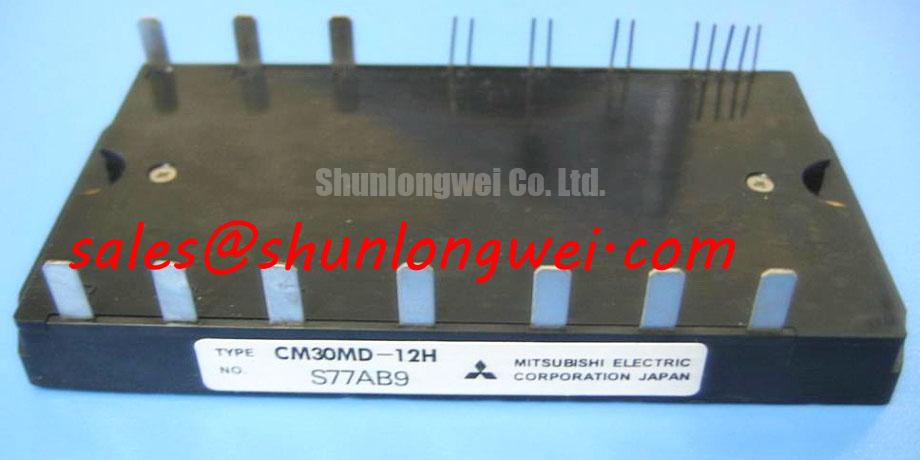
The CM30MD-12H provides a space-saving, low-loss, fully integrated CIB configuration designed to maximize power density in compact industrial motor drives. Featuring a 600V blocking voltage and 30A continuous collector current rating, this module combines a 3-phase input rectifier, a 3-phase inverter, and a brake chopper into a single 100g package with an isolated baseplate.
Top Specs: 600V | 30A | Rth(j-f) 1.9°C/W
Key Benefits:
- Reduces board footprint through high level integration.
- Simplifies thermal management via isolated copper baseplate.
For designers looking to deploy 220V AC input systems, this module provides a complete power stage that answers the need for minimized stray inductance and straightforward mechanical design.
Key Parameter Overview
Decoding the Specs for Enhanced Thermal Reliability
The following table outlines the key technical metrics of the CM30MD-12H CIB module. These specs define the operational limits and switching performance of the integrated converter, brake, and inverter sections.
| Parameter Symbol | Specification Metric | Rating / Value | Engineering Importance |
|---|---|---|---|
| VCES | Collector-Emitter Voltage (Inverter/Brake) | 600V | Determines the maximum DC bus voltage safety margin. |
| IC | Continuous Collector Current (Tj = 25°C) | 30A | Defines continuous current capacity for phase outputs. |
| VCE(sat) | Collector-Emitter Saturation Voltage (Tj = 25°C) | 2.1V (Typical) | Directly influences steady-state conduction losses. |
| Viso | Isolation Voltage (AC 1 Minute) | 2500VRMS | Guarantees electrical safety between active circuits and ground. |
| PC | Maximum Collector Dissipation (per IGBT) | 66W | Determines thermal limits under continuous operation. |
| IFSM | Surge Forward Current (Converter Diode) | 300A | Protects against grid-side startup current surges. |
| Rth(j-f) | Thermal Resistance (Junction-to-Fin, per IGBT) | 1.9°C/W | Governs heatsink matching and thermal dissipation efficiency. |
Download the CM30MD-12H datasheet for detailed specifications and performance curves.
Application Scenarios & Value
Achieving System-Level Benefits in Compact Power Inverters
For 220V AC input industrial applications requiring compact motor control, the 600V 30A rating makes this module the best fit.
Engineers designing low-power industrial equipment face the challenge of minimizing the footprint of the power stage while maintaining high reliability. The CM30MD-12H integrates three distinct power stages—converter, inverter, and brake—into a single Power Module structure. This CIB integration eliminates the need for separate discrete components, reducing layout complexity and mitigating stray inductance that can cause voltage overshoot during switching events. In a typical 3-phase motor drive, the module processes incoming AC power, regulates the DC bus, and drives the motor phases, making it an excellent choice for a servo drive, variable frequency drive (VFD), or compact UPS (Uninterruptible Power Supply).
What is the primary benefit of the integrated CIB layout? It reduces parasitic inductance and saves PCB space. Consider an automated conveyor system where frequent start-stop cycles draw high inrush currents. The converter diodes inside the module boast a surge forward current (IFSM) rating of 300A and a fusing energy (I2t) of 375 A2s. This high energy handling capability ensures the module survives transient motor startup surges without pre-mature fuse failure or device degradation. To learn more about selecting the appropriate module configuration for these layouts, refer to the engineer's guide to IGBT modules.
While the CM30MD-12H is optimized for low-power 30A configurations, projects requiring larger current capability can consider the CM150DY-12H or the CM300DU-12H to meet their power requirements.
Technical Deep Dive
A Closer Look at the Integrated CIB Layout for Electrical Safety
The internal construction of the CM30MD-12H relies on planar IGBT technology and fast recovery free-wheel diodes developed by Mitsubishi. In this layout, the electrical isolation between the power semiconductor chips and the copper baseplate is crucial. With an isolation rating of 2500VRMS, the module provides a robust barrier. The isolated copper baseplate works like a multi-lane highway for heat, routing high thermal energy away from the junction without letting electrical current leak. This layout allows the module to be bolted directly onto a common heatsink with other components, simplifying thermal assembly. Understanding the importance of thermal resistance (Rth) is key to maintaining the junction temperature below the absolute maximum limit of 150°C.
How does the isolated baseplate improve thermal design? It allows mounting multiple semiconductor stages to a single heatsink. Furthermore, the gate-emitter threshold voltage (VGE(th)) rating is specified between 4.5V and 7.5V. This parameter acts like a spring-loaded security gate. Only when the gate control pressure exceeds this threshold will the channel open, preventing noise from accidentally triggering a switch. This relatively high threshold helps shield the system from electromagnetic interference (EMI) generated by high-frequency switching. In designs targeting compliance with demanding standards like IEC 61800-3, engineers must optimize their layout to avoid parasitic turn-on. More information on driving these devices safely can be found in our IGBT gate drive design guidelines.
Frequently Asked Questions
Addressing Critical Integration and Design Queries
How does the Vsub>CE(sat) rating of 2.1V affect the overall efficiency of my converter design?
The collector-emitter saturation voltage (VCE(sat)) of 2.1V dictates conduction losses when the IGBT is fully on. A lower saturation voltage means less energy is dissipated as heat during steady-state conduction, enhancing system efficiency under full-load conditions.
What are the benefits of the 70ns free-wheel diode reverse recovery time?
A fast reverse recovery time of 70ns significantly lowers switching losses during commutation. This enables the inverter part to operate efficiently at higher frequencies, typically up to 20-25 kHz, without causing excessive thermal buildup.
Why is the 375 A2s I2t rating critical for converter protection?
The I2t value of 375 A2s defines the thermal energy limit that the input rectifier diodes can withstand during a short-circuit before failure. This specification is crucial for selecting fast-acting semiconductor fuses to protect the module during line faults.
Can the CM30MD-12H be driven by standard optocoupler gate drivers?
Yes. Thanks to its relatively low gate charge (QG) of 90nC, the module requires minimal gate drive power. It can be easily controlled using standard isolated gate drivers, simplifying drive circuitry and reducing auxiliary power supply demands.
Selecting an integrated CIB module represents a strategic transition toward higher system integration and simplified supply chains for industrial machinery manufacturers. By standardizing on modules like the CM30MD-12H, OEMs can achieve predictable thermal performance and reduced assembly times, positioning their products for modern industrial demands.