
Content last revised on September 16, 2026
Benchtop Waveform Tuning: Mitigating Switching Stress via Reverse-Recovery Behavior on DD171N16K
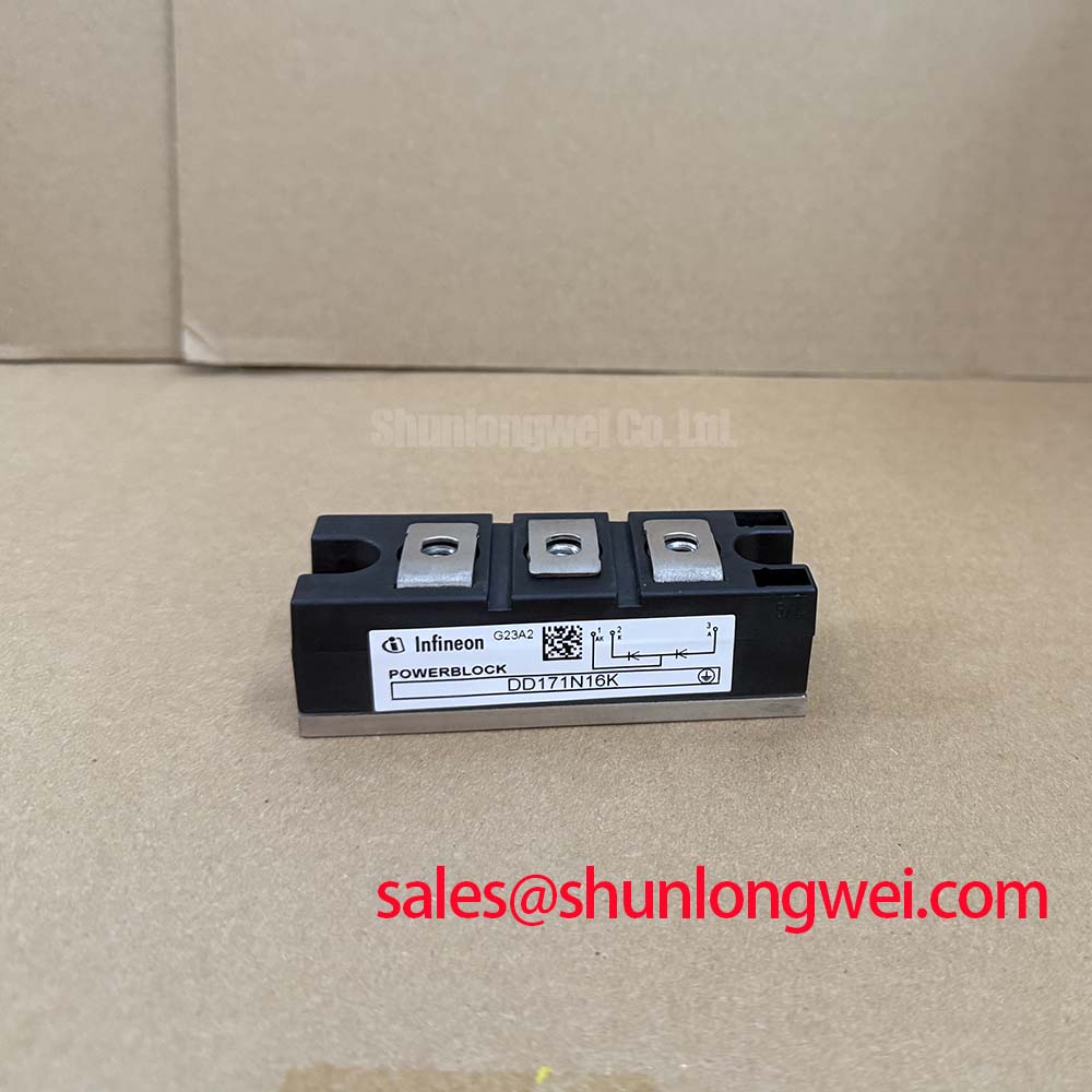
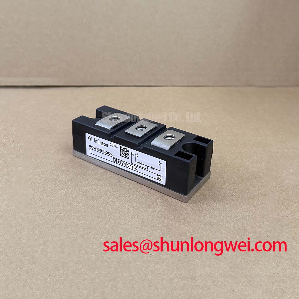
Before connecting DD171N16K to a powered assembly, isolate the module and record its cold-state terminal readings against the known-good rectifier reference, then verify the nameplate rating of 1600 V VRRM. This incoming inspection establishes the polarity and baseline condition of the power path before waveform testing begins.
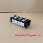
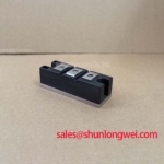
DD171N16K is an Infineon diode module with an official average forward current rating of 171 A at TC = 100°C. Its official repetitive peak reverse voltage is 1600 V, making the voltage rating relevant to high-current rectifier stages connected to 400 V or 480 V class industrial lines, subject to the complete system insulation and transient design. The official surge forward current rating is 5400 A for 10 ms at 25°C. This value is a device specification for the stated test condition, not a substitute for semiconductor fuse coordination.
For bench waveform work, use a current probe and a differential voltage probe with bandwidth and insulation ratings suitable for the test circuit. Observe the commutation interval at the diode terminals and compare reverse recovery current, voltage overshoot, ringing, and recovery behavior with the original reference unit. The available product data supplied for this page does not state a numerical reverse recovery time or peak reverse recovery current for DD171N16K, so those values should be taken from the applicable manufacturer documentation or measured under the specified circuit conditions.
Bench Tip: Use ESD controls during the cold-state comparison and discharge the DC link fully before moving any power or measurement connection.
When a switching bridge shows excessive ringing, the engineering investigation should cover probe placement, busbar geometry, commutation loop inductance, snubber condition, and gate or controller timing elsewhere in the assembly. These observations may indicate a layout or switching interaction rather than a diode defect. The system engineer should verify peak voltage against the rectifier's DC-link operating boundary during controlled switching tests.
Assembly Integrity and Layout Architecture: Semiconductor Protection Fuse Selection for DD171N16K
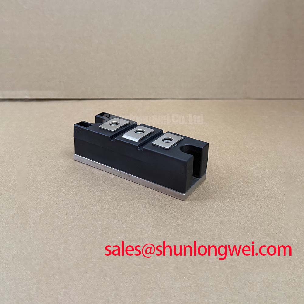
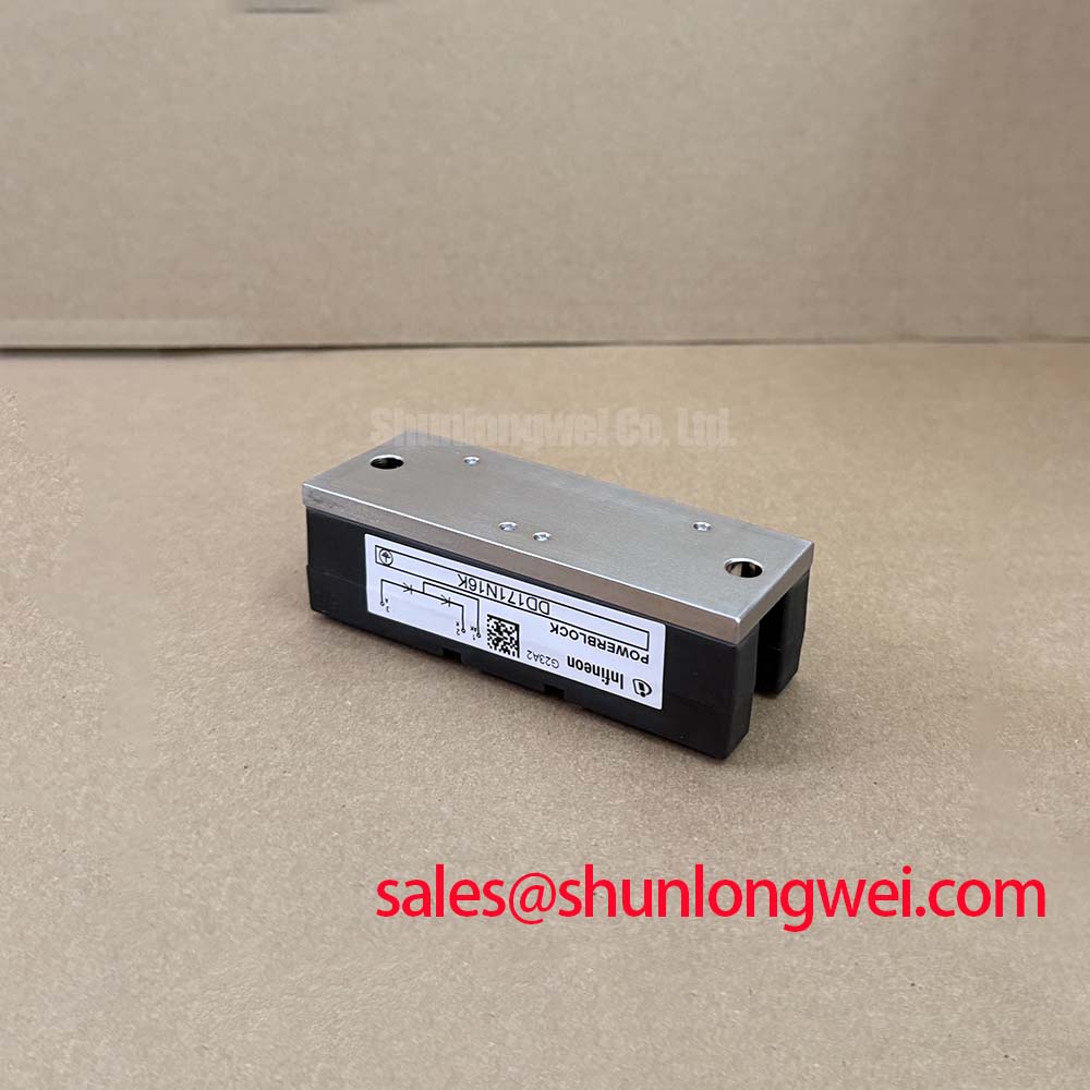
The mechanical installation must maintain reliable thermal and electrical contact across the module base and power terminals. Confirm that the heatsink surface, interface material, clamp arrangement, and terminal hardware follow the applicable Infineon mechanical specification. The supplied product data does not define a mounting torque value, terminal thread, package dimensions, or fuse I²t coordination table; those details must be checked in the exact DD171N16K datasheet and mechanical drawing before assembly.
Fuse selection should be performed by comparing the selected semiconductor fuse's clearing energy with the module's permitted surge and thermal withstand data. DD171N16K carries an official IFSM rating of 5400 A at 10 ms and 25°C, but this rating describes a defined surge test and does not automatically validate every fuse, prospective fault current, ambient temperature, or circuit impedance. The protection study should include the fault waveform, fuse clearing time, current sharing between parallel paths, and the actual repetitive duty cycle.
Keep the high-current path compact and mechanically supported. Minimize parasitic inductance in the fault-current and commutation loops to reduce transient voltage across the diode during interruption and switching. Designers should verify the result with a suitably rated differential probe and should inspect the busbar joints for discoloration, looseness, and uneven contact pressure during scheduled maintenance.
The official maximum forward voltage is 1.26 V at 500 A. This specification is useful when estimating conduction loss and heat removal at the stated test current, but it should not be extrapolated directly to every load condition. Actual temperature evaluation should use the operating current, duty cycle, cooling interface, heatsink performance, and measured electrical behavior of the finished rectifier.
For a high-current green hydrogen electrolyzer DC power rectifier, the module may be evaluated in a line-frequency or controlled rectifier section where fault isolation and service access are important. Compatibility remains system-dependent. The original circuit drawing should be checked for polarity, parallel-device sharing, fuse class, and the physical clearances required by the complete installation.
Preventing Spurious Faults: Pulse-Transformer Isolated Firing Circuit Guidelines for DD171N16K
DD171N16K is specified here as a diode module, so it does not have a gate terminal or a gate-firing requirement. Any pulse transformer, optocoupler, or digital isolator in the surrounding equipment belongs to the controlled rectifier, switching controller, or protection system and must not be treated as an internal feature of this product. This distinction is important when diagnosing an apparently intermittent rectifier fault.
During service testing, trace the complete power path from the controller output through the isolated driver and power stage. Check whether a firing pulse is intended for an associated thyristor or controlled switch, then confirm that the DD171N16K diode terminals receive the expected voltage and current sequence. The relevant test points should be identified from the equipment schematic because the diode module's official data supplied here does not define firing-pulse rise time, holding current, pulse width, or transformer coupling requirements.
A missing or distorted controller pulse may produce abnormal commutation stress, but the same symptom can also arise from incorrect phase sequence, transformer leakage inductance, poor isolation supply regulation, a damaged snubber, or an open power connection. Compare the affected phase with a known-good phase using matched probe settings and a controlled load. Oscilloscope evidence should be correlated with the module's 1600 V repetitive peak reverse voltage boundary and with the voltage rating of every connected semiconductor.
For industrial drive or rectifier control boards, designers should evaluate common-mode transient immunity as a system property of the isolation barrier, layout, cable routing, and grounding arrangement. The diode module itself should not be represented as having an independent EMC or safety certification. Infineon's PrimePACK power semiconductor reference and HybridPACK Drive information provide useful context for comparing power-module integration practices, although they do not change the DD171N16K specifications.
Before reconnecting a controller board, confirm that the DC link is discharged and that all isolation barriers have been tested according to the equipment procedure. This prevents a control-side measurement assumption from becoming a power-terminal safety event.
DD171N16K Thermal-Electrical Optimization: Mitigating DC Ripple in High-Efficiency Rectifier Tuning
Six-pulse and twelve-pulse bridge arrangements can be considered for high-current DC output, but the correct topology depends on the transformer arrangement, phase displacement, harmonic limits, output ripple requirements, and the current-sharing method used by the complete power supply. DD171N16K can be evaluated as a diode element in such a rectifier when its voltage, current, thermal, insulation, and mechanical requirements match the application.
In a six-pulse bridge, inspect each conducting path for balanced current, consistent terminal temperature, and comparable forward-voltage behavior. In a twelve-pulse arrangement, the phase-shifting transformer and any interphase transformer influence current sharing and ripple cancellation. The system engineer should verify the transformer impedance, winding connection, parallel-path resistance, and transient behavior with the intended load rather than assuming equal current distribution from the schematic alone.
Thermal checks should begin with the official electrical data: IFAVM is 171 A at TC = 100°C, while VF is specified as a maximum of 1.26 V at 500 A. These values establish reference points for the thermal study. The finished assembly still requires measured case temperature, interface inspection, airflow or coolant verification, and evaluation of overload duration. Transient thermal impedance, pulse peak junction temperature, and acceptable thermal margin must be taken from the applicable manufacturer documentation and validated against the actual ripple waveform.
The official isolation test voltage is 3000 V AC for 1 minute between the power terminals and baseplate under the stated test condition. It is an insulation test specification, not an operating-voltage guarantee or a complete system certification. Designers should verify creepage, clearance, contamination level, enclosure conditions, altitude effects, and the test method required by the finished equipment standard.
When selecting a replacement or comparing a parallel rectifier option, engineers can review the neutral product listing for DDB6U180N16RRP_B37 as a separate device reference. Its suitability cannot be assumed from package appearance or nominal current alone; voltage class, internal circuit arrangement, thermal interface, terminal geometry, surge capability, and the original equipment schematic must all be checked. For broader topology considerations involving resonant and half-bridge equipment, the Resonant Topologies in Home Appliances guide offers additional system-level context without replacing the DD171N16K datasheet.